
Resistor Transistor Logic (RTL)
Resistor Transistor Logic (RTL) is one of the early digital logic families developed for implementing basic logic functions using resistors and bipolar junction transistors (BJTs). It was the first monolithic integrated circuit originally introduced by Fairchild in the year 1961.
In an RTL circuit, resistors are primarily used to combine the input signals and control the transistor current, while the transistor performs the switching and amplification required to produce the logic output. It is popular because of its simplicity.
Resistor Transistor logic – 2 input NOR gate
Resistor Transistor Logic is a bipolar saturated device. The RTL circuit consists of resistors at inputs and transistors at the output side. Transistors are used as the switching device. The emitter of the transistor is connected to the ground. The collector terminals are tied together and given to the supply through the resistor RC. The collector resistor is known as a passive pull-up resistor.
The following figure shows the circuit diagram of 2-input RTL NOR gate. Q1 and Q2 are the two transistors. A and B are the two inputs, given to the base of two transistors and Y is the output.
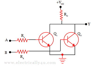
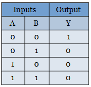
When both the inputs A and B are at 0V or logic 0, it is not enough to turn on the gates of both the transistor. So the transistors will not conduct. Due to this, the voltage +VCC will appear at the output Y. Hence the output is logic 1 or logic HIGH at terminal Y.
When any one of the inputs, either A or B is given HIGH voltage or logic 1, then the transistor with HIGH gate input will be turned on. This will make a path for the supply voltage to go to the ground through the resistor RC and transistor. Thus there will be 0 v at the output terminal Y.
When both the inputs are HIGH, it will drive both the transistor to turn on. It will make a path for the supply voltage to flow to the ground through resistor RC and transistor. Therefore, there will be 0 v at the output terminal Y.
The below table shows the truth table for NOR gate.
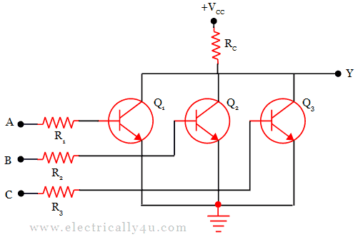
Resistor Transistor Logic – 3 input NOR gate
The above discussed 2-input RTL NOR gate is the basis for all the logic circuits built with resistors and transistors. The 3-input Resistor Transistor Logic NOR gate can also be constructed as shown below. The operation is similar to the 2-input RTL NOR gate.
Advantages
The digital logic family based on resistor transistor logic offers several benefits, particularly because of its simple circuit construction and low component requirement.
- Simple circuit design: RTL circuits use a relatively less number of transistors and resistors, making their basic design easy to understand and implement.
- Low component count: A limited number of semiconductor devices are required to perform logic operations, which simplifies the overall circuit.
- Low cost: The simple construction of RTL gates makes them inexpensive to manufacture and suitable for basic digital applications.
- Easy implementation: RTL circuits can be designed and constructed using straightforward resistor-transistor configurations.
- Availability of complementary signals: Both the original and inverted forms of a signal can be obtained conveniently from suitable RTL configurations.
- Reduced semiconductor usage: The basic RTL approach can perform logic operations with fewer active semiconductor components compared with some more complex circuit arrangements.
- Useful for understanding digital logic: Although RTL is largely obsolete in modern systems, its simple structure makes it useful for studying the fundamentals of transistor-based digital circuits.
Disadvantages
Despite its simple construction, RTL has several limitations that have led to the adoption of more advanced digital logic families, particularly TTL and CMOS.
- High power consumption: RTL circuits can consume considerable power, especially when their transistors are in the conducting state.
- High current dissipation: Excessive current may flow through the transistor and associated resistors under certain operating conditions, resulting in increased power losses.
- Limited fan-in: RTL gates cannot conveniently accommodate a large number of inputs because increasing the number of inputs affects circuit performance.
- Low switching speed: The presence of relatively large resistive-capacitive time constants causes RTL circuits to operate more slowly than many modern logic families.
- Poor noise immunity: RTL circuits are comparatively sensitive to electrical noise and interference, which can affect the reliability of logic signals.
- Limited compatibility: Their logic voltage levels and operating characteristics can restrict direct interfacing with other logic technologies.
- Performance limitations: RTL generally provides poorer speed, power efficiency, and overall performance than modern digital logic families such as TTL and CMOS.
- Largely obsolete: Due to these limitations, RTL has been replaced in most practical applications by more efficient logic technologies such as TTL, CMOS, and other advanced semiconductor logic families.





Thanks for all these