
Hamming code with solved problems
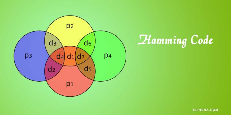
Hamming Code in computer network is one of the most widely used error detection and correction codes. It was originally invented by Richard W. Hamming in the year 1950. The Hamming code algorithm improves communication reliability while requiring only a small amount of additional data.
It is used to detect and correct single-bit errors during binary data transmission by adding extra parity bits called redundant bits, to the original data.
The redundant bits are extra bits that are placed at certain locations of the data bits to detect the error. At the receiver end, the code is decoded to detect and correct errors, and the original data is retrieved. These bits are used to ensure that no bits were lost during data transfer.
So before transmitting, the sender has to encode the data with the redundant bits. It involves three steps, as described below.
Hamming code algorithm
Before initiating the encoding process, it is important to make sure that the information is in binary form. If not, it has to be converted into its binary form. The algorithm of hamming code in computer network is explained as follows.
Selecting the number of redundant bits
The first step in encoding process is determining the number of redundant bits required for reliable error correction. The hamming code uses these redundant bits to detect and correct errors during binary data transfer.
The number of redundant bits depends on the number of information (data) bits in the message. Let n be the number of information carrying bits. Then, the minimum number of redundant bits is calculated using the following hamming code formula.
![\[2^P \geq n + P + 1 \]](https://elpedia.com/wp-content/ql-cache/quicklatex.com-854cf2500e2a09e3a66a0d629dbd1b36_l3.png "Rendered by QuickLaTeX.com")
For example, if 4 bit information is to be transmitted, then n=4. The number of redundant bits is determined by the trial and error method.
Let P=2, we get,
![\[2^2 \geq 4 + 2 + 1 \]](https://elpedia.com/wp-content/ql-cache/quicklatex.com-c3f694d46fd7307f6704f0540ae715f4_l3.png "Rendered by QuickLaTeX.com")
The above equation implies that 4 is not greater than or equal to 7. So let’s choose another value of P=3.
![\[2^3 \geq 4 + 3 + 1 \]](https://elpedia.com/wp-content/ql-cache/quicklatex.com-b720f0f01ef38c83f20b1a14e0e3a2b4_l3.png "Rendered by QuickLaTeX.com")
Now, the equation satisfies the condition. So 3 redundancy bits are required for this hamming code calculation.
In this way, the number of redundant bits is determined for the number of information bits to be transmitted before encoding with hamming code.
Choosing the location of redundant bits
Once the required number of parity bits has been calculated, the next step in the hamming code algorithm is placing the redundant data bits in the correct positions.
For the above example, the number of data bits n=4, and the number of redundant bits P=3. So the message consists of 7 bits in total that are to be coded. Let the rightmost bit be designated as bit 1, the next successive bit as bit 2 and so on.
The seven bits are bit 7, bit 6, bit 5, bit 4, bit 3, bit 2, bit 1.
In this, the redundant bits are placed at all the bit positions that are numbered corresponding to the power of 2, i.e., 1, 2, 4, 8,… These positions are marked as parity bits and the exact location of data bit and redundant bit are D4, D3, D2, P3, D1, P2, P1.
Placing the extra binary bits in these fixed locations allows the hamming code decoder to quickly identify the position of an erroneous bit during error detection and correction.
Assigning the values to redundant bits
Now the next step in hamming code error detection is to assign bit value to the redundant bits in the formed code group. The assigned bits are called a parity bit.
A parity bit is an extra binary bit added to a data sequence to make the total number of 1s either even or odd. It is commonly used for error detection and error correction codes.
In even parity, if the total number of 1s in the original data is odd, the parity bit is set to 1 to make the total count even. If the number of 1s is already even, the parity bit is set to 0. In this case, the added bit is called even parity bit.
Similarly the data set is checked for odd parity and an odd parity bit is set so that the total number of 1s in the data, including the parity bit, is odd.
Each parity bit will check certain other bits in the total code group, whether it contains an even or odd number of 1s. Depending on the system, either even or odd parity is used.
The bit location table is drawn as shown below.
| Bit Location | 7 | 6 | 5 | 4 | 3 | 2 | 1 |
| Bit designation | D4 | D3 | D2 | P3 | D1 | P2 | P1 |
| Binary representation | 111 | 110 | 101 | 100 | 011 | 010 | 001 |
| Information / Data bits | D4 | D3 | D2 | D1 | |||
| Parity bits | P3 | P2 | P1 |
Parity bit P1 covers all the bits positions whose binary representation has 1 in the least significant bit position(001, 011, 101, 111, etc.). Thus P1 checks the bit in locations 1, 3, 5, 7, 9, 11, etc..
Parity bit P2 covers all the bits positions whose binary representation includes 1 in the second least significant position(010, 011, 110, 111, etc.). Thus P2 checks the bit in locations 2, 3, 6, 7, etc.
Parity bit P3 covers all the bits positions whose binary representation has 1 in the third least significant position(100, 101, 110, 111, etc.). Thus P3 checks the bit in locations 4, 5, 6, 7, etc.
Each parity bit covers all the bit positions and assign the parity bit value as 1 or 0, so as to make the number of 1s as even for even parity and odd for odd parity.
This parity checking process is the foundation of the hamming code algorithm and enables efficient single-bit error detection.
Now let us look at a solved example of encoding hamming code.
Example problem 1
Encode a binary word 11001 into the even parity hamming code.
Given, number of data bits, n =5.
To find the number of redundant bits,
Let us try P=4.
![\[2^4 \geq 5 + 4 + 1 \]](https://elpedia.com/wp-content/ql-cache/quicklatex.com-05825b40347f4bf839aac0ead2c68e74_l3.png "Rendered by QuickLaTeX.com")
The equation is satisfied and so 4 redundant bits are selected.
So, total code bit = n+P = 9
The redundant bits are placed at bit positions 1, 2, 4 and 8.
Construct the bit location table.
| Bit Location | 9 | 8 | 7 | 6 | 5 | 4 | 3 | 2 | 1 |
| Bit designation | D5 | P4 | D4 | D3 | D2 | P3 | D1 | P2 | P1 |
| Binary representation | 1001 | 1000 | 0111 | 0110 | 0101 | 0100 | 0011 | 0010 | 0001 |
| Information bits | 1 | 1 | 0 | 0 | 1 | ||||
| Parity bits | 1 | 1 | 0 | 1 |
To determine the parity bits
For parity bit 1: Bit locations 3, 5, 7 and 9 have three 1s. To have even parity, P1 must be 1.
For Parity bit 2: Bit locations 3, 6, 7 have two 1s. To have even parity, P2 must be 0.
For Parity bit 3: Bit locations 5, 6, 7 have one 1s. To have even parity, P3 must be 1.
For Parity bit 4: Bit locations 8, 9 have one 1s. To have even parity, P2 must be 1.
Thus the encoded 9-bit hamming code is 111001101.
How to detect the error?
After receiving the encoded data, each parity bit along with its corresponding group of bits are checked for proper parity. While checking, the correct result of individual parity is marked as 0 and the wrong result is marked as 1.
After checking all the parity bits, a binary word called syndrome is formed taking the result bits for P1 as LSB. So formed binary word gives the bit location, where there is an error.
If the formed binary word is 0000, then there is no error in the received data. This process allows hamming code decoding to accurately detect and correct any single-bit error without retransmitting the message.
Example problem 2
Let us assume the even parity hamming code from the above example (111001101) is transmitted and the received code is (110001101). Now from the received code, let us identify and correct the error.
To detect the error, let us construct the bit location table.
| Bit Location | 9 | 8 | 7 | 6 | 5 | 4 | 3 | 2 | 1 |
| Bit designation | D5 | P4 | D4 | D3 | D2 | P3 | D1 | P2 | P1 |
| Binary representation | 1001 | 1000 | 0111 | 0110 | 0101 | 0100 | 0011 | 0010 | 0001 |
| Received code | 1 | 1 | 0 | 0 | 0 | 1 | 1 | 0 | 1 |
The given data set is checked for even parity
For P1 : Check the locations 1, 3, 5, 7, 9. There is three 1s in this group, which is wrong for even parity. Hence the bit value for P1 is 1.
For P2 : Check the locations 2, 3, 6, 7. There is one 1 in this group, which is wrong for even parity. Hence the bit value for P2 is 1.
For P3 : Check the locations 3, 5, 6, 7. There is one 1 in this group, which is wrong for even parity. Hence the bit value for P3 is 1.
For P4 : Check the locations 8, 9. There are two 1s in this group, which is correct for even parity. Hence the bit value for P4 is 0.
The resultant binary word is 0111. It corresponds to the bit location 7 in the above table. The error is detected in the data bit D4. The error is 0 and it should be changed to 1. Thus the corrected code is 111001101.
This example illustrates how the Hamming code algorithm performs error detection and correction by locating and correcting a single erroneous bit, ensuring reliable data transfer in computer network.
Advantages of Hamming Code
Hamming code in computer networks offers several advantages, making it a widely used error detection and correction technique:
- Single Error Correction: Hamming code is capable of detecting and correcting single-bit errors that occur during data transfer or storage, ensuring data integrity.
- Efficient Error Detection: It can detect the errors caused by noise, electromagnetic interference, or other external factors that may corrupt the data.
- Improves Reliability: By adding redundant parity bits, Hamming code enhances the reliability of communication systems, reducing the need for retransmission.
- Low Overhead: It requires only a small number of extra bits (redundant bits) relative to the data bits, making it an efficient code.
- Simple Implementation: The algorithm is straightforward to implement in hardware or software, facilitating real-time error correction in various digital systems.
- Automatic Error Correction: Unlike simple parity checks that only detect errors, Hamming code can automatically do the error correction without additional communication between sender and receiver.
- Widely Applicable: It is used in memory systems, telecommunications, computer networks, and other digital storage applications where data integrity is critical.
These advantages make Hamming code an ideal choice for error detection and correction in computer networks, ensuring data is transmitted accurately and efficiently.
Applications of Hamming Code
It is widely used in various fields and applications where data integrity and error correction are critical. Some common applications include:
- Computer Memory (ECC Memory): Hamming code is extensively used in Error-Correcting Code (ECC) memory modules in computers to detect errors that occur due to hardware faults or cosmic rays, ensuring reliable memory operations.
- Digital Communication Systems: It is employed in digital communication to detect errors that occur during the transmission of data over noisy channels.
- Data Storage Devices: Hard drives, solid-state drives, and other storage media use Hamming code to maintain data integrity by correcting errors that may arise during data storage or retrieval.
- Satellite and Space Communication: In space communication where retransmission is costly or impossible, this code helps in error detection and correction to maintain data accuracy.
- Networking: Used in computer networks to enhance the reliability of data packets transmitted across the network by detecting and correcting transmission errors.
- Wireless Communication: Helps in improving data reliability in wireless communication systems by correcting errors caused by interference and signal degradation.
- Embedded Systems: In microcontrollers and embedded systems, this code is used to ensure error-free data processing and storage.
These applications leverage the ability of Hamming code to detect the errors efficiently with minimal overhead, making it a fundamental technique for error control in digital systems.



Thank you very much for declaration of Hamming code and the parity’s position
Thanks a lot for the explanation on finding the redundant bits.
Thankyou for your meaningful notes
Glad to hear this. Thank you.