What is a multiplexer? Operation, types and applications
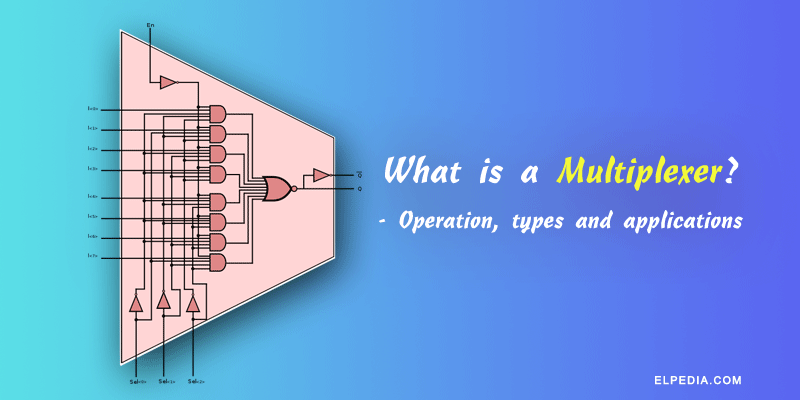
A multiplexer (MUX) is a combinational logic circuit, which selects and delivers a single input as output from multiple input lines. It performs the similar operation of a switch. Hence, we can call it a digital switch.
In digital systems, several digital signals may be available at the same time, but only one of them may need to be transmitted or processed. There comes a need for a multiplexer circuit, which has multiple input lines and a single output line.
What will you learn:
- The fundamental concept and operation of a multiplexer in digital electronics.
- The structure and working of a different types of multiplexer.
- How selection lines control the routing of input signals to the output.
- The Boolean expressions and truth tables associated with multiplexers.
- Implementation of multiplexers using logic gates.
- How to cascade lower-order multiplexers to create higher-order multiplexers.
- Common applications of multiplexers in data selection, routing, data communication systems, and digital logic design.
- Understanding multiplexer ICs and their functions.
What is a multiplexer?
Digital multiplexers are also known as a data selector because they are used to select the digital signals that has to be sent to the output line. Digital multiplexers route discrete binary signals, while analog multiplexers can route both AC and DC signals.
The multiplexer selects a particular input with the help of a control signal and routes it to the output. In general, a multiplexer has 2n inputs and n selection lines and one output.
For example, a 4 : 1 multiplexer has four data inputs, two selection lines, and one output. Similarly, an 8 : 1 multiplexer has eight data inputs, three selection lines, and one output.
The below diagram represents the general circuit for 2n : 1 mux circuit. It has 2n data inputs(D0, D1, D2, … D2n-1), n selection inputs(S0, S1,… Sn), 1 enable input(E) and one output(Y).
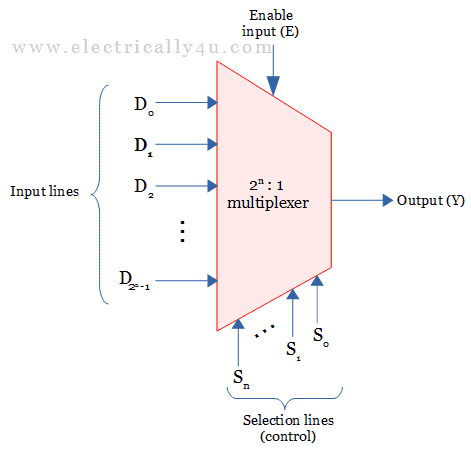
There are different types of multiplexers like 2 to 1 multiplexer, 4 to 1 multiplexer, 8 to 1 multiplexer and so on depending on the number of input data lines
For better understanding of the multiplexer circuits, let us look at some of the types.
2 : 1 multiplexer
The 2 : 1 multiplexer has two input lines (D0, D1), two select line (S) and one output line (Y). The block diagram and the circuit for 2 to 1 multiplexer is shown below.
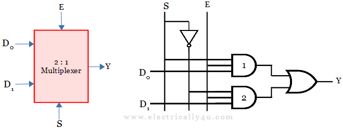
When enable input is set to 0, the mux will not work. Enable should be set to 1, to get the output from the mux.
When the selection input S=0, it gets applied to the first AND gate. The output of this AND gate(1) is 0 irrespective of the other input. The inverted S input (S=1) is applied to the second AND gate(2), whose output will be equal to D1.
When S = 1, it is directly applied to AND gate(1), the output of the gate will be equal to D0. The inverted S input(0) is applied to the second AND gate(2). Thus the output of the AND gate(2) will be 0 irrespective of the other input.
Thus, when S=0, second AND gate is enabled and when S=1, first AND gate is enabled. The operation is explained with the function table below.
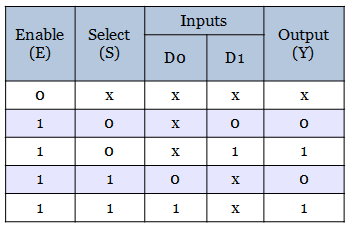
From the function table, it is clear that, the output Y = 1, when ES’D1 = 1 and ESD0 = 1.
The output Boolean equation for 2 to 1 multiplexer is found to be,
![\[ Y = E \overline{S} D_1 + ES D_0 \]](https://elpedia.com/wp-content/ql-cache/quicklatex.com-ba4e27a206e0fa4e13c33b94ed68bae1_l3.png "Rendered by QuickLaTeX.com")
4 : 1 multiplexer
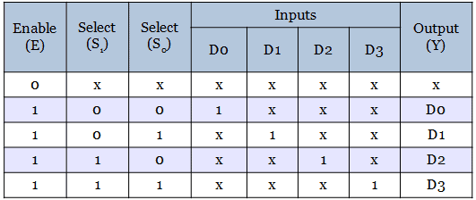
A 4 : 1 multiplexer has four data input lines (D₀, D₁, D₂ and D₃), two selection lines (S₁ and S₀), and single output line (Y).
The two selection lines can produce four different binary combinations. Each combination enables one of the four input paths and transfers the corresponding input signal to the output. The following figure illustrates its block giagram and circuit diagram.
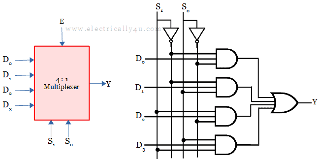
For selection inputs, S1S0 = 00, first AND gate alone is enabled and the output produced is
![\[ Y = D_0\overline{S_1}\overline{S_0} \]](https://elpedia.com/wp-content/ql-cache/quicklatex.com-f0612badfb7c5cb1570a4e00d89b1b38_l3.png "Rendered by QuickLaTeX.com")
For the next selection input S1S0 = 01, Second gate alone is enable, whose output is given by
![\[ Y = D_1\overline{S_1}S_0 \]](https://elpedia.com/wp-content/ql-cache/quicklatex.com-b934b38111ae466fcb542fcba49f8931_l3.png "Rendered by QuickLaTeX.com")
When selection input S1S0 = 10, all the AND gates are disabled except the third gate from the top. The output will be
![\[ Y = D_2{S_1}\overline{S_0} \]](https://elpedia.com/wp-content/ql-cache/quicklatex.com-8bd406ea9417c1776c4a99e867eb3223_l3.png "Rendered by QuickLaTeX.com")
The fourth gate gets enabled for the selection input S1S0 = 11 and the output will be
![\[ Y = D_3{S_1}{S_0} \]](https://elpedia.com/wp-content/ql-cache/quicklatex.com-baa6d7c553ea24963d21a86643a8c690_l3.png "Rendered by QuickLaTeX.com")
Any type of boolean function can be implemented by using a multiplexer. For a better understanding of the implementation, some problems are solved in multiplexer.
Multiplexer ICs
There are several integrated circuits (ICs) designed to perform multiplexing operations for different types of multiplexers. These ICs simplify the implementation of multiplexers in digital systems by providing ready-made circuits with multiple inputs, select input lines, and output lines.
Some common multiplexer ICs include:
- IC 74150: A 16:1 multiplexer with sixteen data inputs, four select inputs, and one output. It is used for selecting one input from multiple data inputs.
- IC 74151: An 8:1 multiplexer with eight data inputs, three select inputs, and one output. It is widely used for data routing and selection in digital circuits.
- IC 74153: A dual 4:1 multiplexer with two sets of four data inputs, two select lines, and two outputs. It is useful for applications requiring multiple data selections.
- IC 74157: A quad 2:1 multiplexer with four pairs of data inputs, one select input, and four outputs. It is commonly used for selecting between multiple data sources.
All these ICs have control inputs such as enable pins that allow the multiplexer to be activated or disabled. These ICs simplifies the design of complex circuits by reducing the number of discrete components needed and providing reliable data routing and selection functionality.
Applications of Multiplexer
A multiplexer is an important combinational circuit widely used in digital circuits for various applications. Some key applications include:
- Data selection and routing: Multiplexers select one input from multiple digital inputs and connect it to the common output line. This output based selection helps in routing multiple input signals through a single transmission line efficiently.
- Time division multiplexing (TDM): Multiplexers enable time division multiplexing by allowing multiple devices to share a single transmission line sequentially, maximizing the use of communication channels.
- Digital communication systems: Multiplexers are used to combine multiple signals into one line for transmission, reducing the number of physical lines and control lines required.
- Implementation of Boolean functions: Multiplexers can implement any boolean function and logic function including not gate, exnor gate and so on by connecting digital inputs and selector inputs appropriately, making them universal combinational circuits.
- Cascading multiplexers: Larger multiplexers like 8:1, 16:1, and 64:1 can be formed by cascading smaller multiplexers, allowing maximally control over several inputs with fewer selector pins.
- Processor and computer systems: Multiplexers select data between registers, memory locations, or multiple devices to a common output, facilitating data select operations.
- Signal switching and control: Multiplexers switch logic values from multiple sources to a single output based on selector inputs, useful in digital control systems.
- Digital audio and video applications: Multiplexers route digital audio or video signals, allowing multiple sources to share a single channel.
- Parallel-to-serial conversion: Multiplexers convert parallel data inputs into serial data output by selecting data inputs sequentially.
- Demultiplexing reverse process: Multiplexers’ reverse process, demultiplexers, distribute single input to several output lines, often used alongside multiplexers in communication.
The procedure of using multiplexers and demultiplexers facilitates efficient data transmission and digital signal management in complex digital systems.