Losses in DC machine
An electrical machine converts energy from one form to another. Losses in DC machine occur because it does not convert all the input energy into useful output energy. As you know, a DC generator converts mechanical energy into electrical energy, while a DC motor converts electrical energy into mechanical energy.
During this energy conversion, some energy is lost mainly in the form of heat. These unwanted energy losses are called power losses. The basic power relationship of a DC machine is:
Input Power = Output Power + Power Losses
Power losses cause the machine to heat up. If the losses become too high, the temperature of the machine may rise beyond its safe operating limit, which can damage the insulation and other components. Therefore, it is more useful to study power losses rather than energy losses because power loss shows the rate at which energy is being lost.
In this article, we will discuss the different type of losses that will occur in dc machines and its importance.
Classification of Power Losses in dc machine
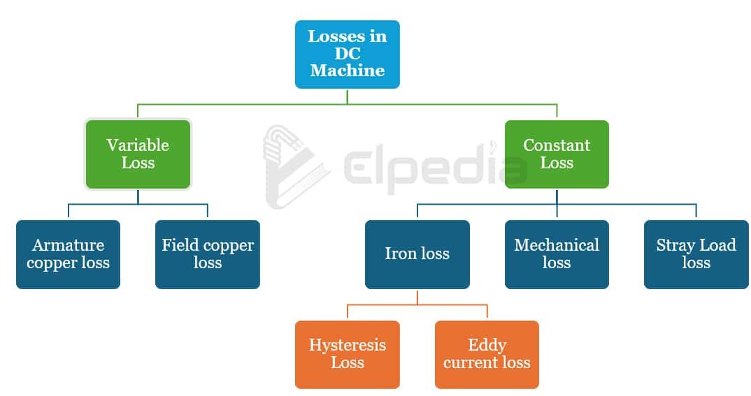
The losses in dc machines are classified as constant losses and variable losses.
Losses that change with the load current are called variable losses. They mainly include copper loss or electrical loss that occur in the armature and field windings. Since these losses depend on current (I2), they increase significantly as the load current increases.
Losses that remain approximately constant when the machine operates at nearly constant speed, flux, and voltage are called constant losses. These generally include iron or core losses, mechanical losses, stray load losses and shunt field copper loss.
The different types of losses in DC machine is summarized in the diagram below,
Electrical or copper loss
Copper losses in dc machine mainly occur in armature winding, shunt field winding, series field winding, interpole winding, compensating winding and brush contacts.
Electrical losses occur because current flows through the mentioned resistive parts of the machine. The resistance of the windings causes electrical energy to be converted into heat.
The actual copper loss depends on the effective resistance of the winding during operation. This resistance changes with the load and excitation conditions, making it difficult to find its exact value. Therefore, copper losses are usually calculated using the DC resistance of the winding at 75°C. Copper losses are generally divided into armature copper loss and field copper loss.
Armature Copper Loss
The armature copper loss is given by
![\[P_{cu} = I_a^2 \, R_a \]](https://elpedia.com/wp-content/ql-cache/quicklatex.com-2d07240b6a5b021e5c6a0f9d37d69ffb_l3.png "Rendered by QuickLaTeX.com")
where Ia is the armature current and Ra is the armature resistance. The brush contact resistance is generally included in the effective armature resistance. Since armature copper loss is proportional to the square of armature current, it increases rapidly when the load increases. At full load, armature copper loss may form a significant portion of the total machine losses.
Field Copper Losses
Field copper losses occur in different field windings of the DC machine including shunt field windind, interpole winding, seires field winding, interpole winding and compensating winding.
For a shunt field winding, the copper loss is given by an equation Psh = Ish2Rsh. Here Ish is the shunt field current and Rsh is the shunt field resistance. In a shunt and compound machine, this loss remains approximately constant, when operating at same applied voltage.
The copper loss in the series field winding is given by Pse = Ise2Rse. Here Ise is the series field current and Rse is the series field resistance. This loss occurs in series and compound DC machines.
For the interpole winding, the copper loss is given by Pin = Ia2Rin, where Ia is the armature current and Rin is the interpole winiding resistance. This loss occurs only in machines provided with interpoles.
Similarly for compensating winding, the electrical loss is given by Pco = Ia2Rco, where Ia is the armature current and Rco is the compensating winiding resistance.
As the machine load increases, the armature current also increases. Therefore, losses in the armature, interpole, series field, and compensating windings also increase.
Iron or Magnetic Losses
Iron losses in dc machine also called core losses, occur in the iron parts of the machine because of the continuously changing magnetic flux, as the armature rotates. The two major types of iron losses are Hysteresis loss and Eddy current loss.
Hysteresis Loss
As the armature rotates, different portions of the armature core repeatedly pass through the magnetic field of the poles. This causes repeated magnetization and demagnetization of the core.
The energy lost during this repeated process is called hysteresis loss. It can be expressed approximately as,
Phy = η Bmax1.6 f v
where η is the Steinmetz hysteresis coefficient, Bmax is the maximum flux density, f is the frequency of magnetic reversals and v is the volume of the core. The frequency of magnetic reversals is related to the speed of the machine by f = PN/120, where P indicates the number of poles and N represents the speed in rpm.
Hysteresis loss increases with magnetic flux density and the frequency of magnetic reversals. To reduce this loss, the armature core is made from magnetic materials having a low hysteresis coefficient, such as silicon steel.
Eddy Current Loss
When the armature core rotates in the magnetic field, an emf is induced in the iron core. This emf produces small circulating currents within the core. These currents are called eddy currents, and the resulting power loss is known as eddy current loss.
The approximate expression for eddy current loss is given by,
Pe = Ke Bmax2 f2 v t2
where Ke is the eddy current constant, Bmax is the maximum flux density, f is the frequency of magnetic variation, v is the volume of magnetic material and t is the thickness of the lamination.
An important point is that eddy current loss varies with the square of lamination thickness. Therefore, the armature core is constructed using many thin laminations. The individual laminations are electrically insulated from one another, usually using a thin insulating coating. This construction significantly reduces the circulating eddy currents and hence reduces the power loss.
Mechanical Losses
Mechanical losses in dc machine occur due to friction and air resistance in the moving parts. The main mechanical losses include bearing friction, brush friction and windage loss.
Bearings experience friction when the shaft rotates. Good quality bearings and proper lubrication help reduce this loss. Improper lubrication can increase friction and cause additional heating and wear.
In a commutator type DC machine, the brushes remain in contact with the rotating commutator. Friction between the brushes and commutator produces mechanical loss. The amount of brush friction depends on factors such as brush material, pressure, and machine speed.
The rotating armature has to move through the surrounding air. The power required to overcome this air resistance is called windage loss. Machines may also use rotating fans or blades to improve cooling. Moving a larger quantity of air requires additional power. Windage loss increases significantly with speed and is approximately proportional to the cube of speed.
Stray load Loss
Some additional losses occur when the machine operates under load. These are known as stray load losses. They can result from several effects, including:
- Distortion of the magnetic flux due to armature reaction
- Unequal current distribution in the armature conductors
- Additional currents in coils during the commutation process
Because these losses are difficult to calculate accurately, they are often estimated using an assumed percentage of the machine output. For large machines, stray load loss may be considered as a small percentage of the output. In smaller machines, it may often be neglected for practical calculations.
Summary of losses in dc machine
| Type of loss | Nature of loss | Main cause | Approximate loss percentage |
|---|---|---|---|
| Armature copper loss | Variable | Resistance of armature winding | 30–40% |
| Field copper loss | Partly constant / variable | Resistance of field windings | 20–30% |
| Hysteresis loss | Constant* | Repeated magnetization and demagnetization of the core | Included in 20–30% core losses |
| Eddy current loss | Constant* | Circulating currents induced in the armature core | Included in 20–30% core losses |
| Mechanical loss | Constant* | Bearing friction, brush friction and windage | 10–20% |
| Stray load loss | Variable | Armature reaction, uneven current distribution and commutation effects | About 1% of output for machines rated around 150 kW or more |
*For a machine operating at approximately constant speed and flux.
Why Power Losses Matter
The above discussed losses in DC machine directly affect its performance and efficiency. Higher losses can result in:
- Lower operating efficiency
- Increased heat generation
- Higher temperature rise
- Increased energy consumption
- Reduced machine life
- Possible damage to insulation and components
Therefore, reducing power losses in DC machine is important for improving its efficiency, reliability, and operating life. Using suitable magnetic materials, thin core laminations, good-quality bearings and brushes, effective cooling, and proper operating conditions can help reduce these losses.