Power flow in dc machine
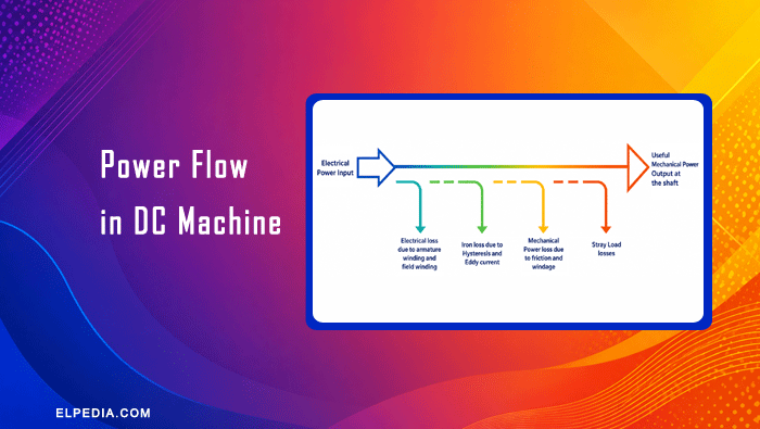
Power flow in DC machine represents the sequence in which power is transferred, converted, and lost as it moves through the machine.
In order to analyze the operation and performance of electrical machines, it is important to understand the sequence of energy conversion. Under steady-state operation, a machine receives input power at a specific rate. A portion of this power is lost as heat due to copper, iron, and mechanical losses.
The remaining power is converted into useful output and supplied to the load. Depending on the type of machine, the main energy conversion occurs in one of two ways.
A DC machine can operate either as a DC generator or a DC motor. In a DC generator, mechanical power supplied by the prime mover is converted into electrical power.
In a DC motor, electrical power supplied to the machine is converted into mechanical power. In both cases, a part of the input power is lost as heat due to copper losses, iron losses, mechanical losses, and stray load losses. These losses are discussed in the previous article. Read it for clear understanding.
In this article, you will learn about the power flow in dc machine and the power flow diagram.
Power Flow in a DC Generator
In a DC generator, mechanical power is supplied to the shaft by a prime mover. During rotation, some mechanical power is consumed by mechanical and iron losses. The remaining mechanical power is converted into electrical power through electromagnetic action.
A part of the generated electrical power is then lost as copper losses in the armature and field windings. The remaining power is delivered to the external load as useful electrical output power.
Thus, the general power flow in a DC generator can be represented as:
Mechanical power input → Mechanical and iron losses → Electromagnetic conversion → Copper and stray load losses → Useful electrical power output
Power Flow in a DC Motor
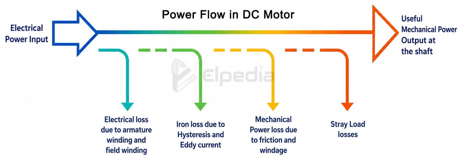
In a DC motor, electrical power is supplied to the armature and field windings. A portion of the input electrical power is lost as copper losses. The remaining electrical power is converted into mechanical power through electromagnetic action.
After conversion, some of the mechanical power is consumed by mechanical, iron, and stray load losses. The remaining power is available as useful mechanical output at the motor shaft.
The general power flow in a DC motor can be represented as:
Electrical power input → Copper losses → Electromagnetic conversion → Mechanical, iron, and stray load losses → Useful mechanical power output
Losses during power flow in dc machine
The main losses considered in the power flow in DC machine are:
- Copper losses: These occur due to the resistance of the armature and field windings when current flows through them.
- Iron losses: These include hysteresis and eddy-current losses in the magnetic parts of the machine.
- Mechanical losses: These are caused by friction in bearings and brushes and by windage during rotation.
- Stray load losses: These are additional losses caused by the effects of load current and leakage flux that are not included in the main copper and iron losses.
The position of each loss in the power flow depends on the form of energy responsible for producing that loss. Copper losses originate from electrical energy, while mechanical losses are associated with mechanical energy. This principle helps determine where each loss occurs in the energy conversion process.
Power flow diagram of dc machine
A power flow diagram gives a graphical representation of how input power is converted into useful output power and how different losses occur during the conversion process.
It makes the energy conversion process easier to understand and helps in determining the efficiency of a DC machine. The power flow diagrams for a DC generator is shown below.
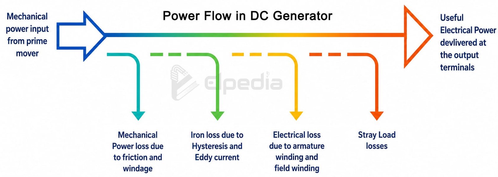
The power flow diagrams for a DC motor is shown in the following figure. These diagrams clearly indicate the input power, energy conversion, individual losses, and useful output power of the machine.