Commutation in DC Machine
Commutation in DC machine is one of the most important processes in electrical machine. It ensures that current flowing in the armature conductors of a dc machine reverses smoothly as the rotor rotates. Without proper commutation, a DC motor or generator experiences excessive sparking at the brushes, leading to reduced efficiency, overheating, brush wear, and damage to the commutator.
In this article, we’ll explore the concept of commutation in DC machine, understand how it works, discuss the reasons behind poor commutation, and learn the practical methods used to improve it.
What is Commutation?
The commutator and brushes are essential parts of a DC machine. They perform two important functions.
- First, they transfer electric current between the rotating armature and the external circuit.
- Second, they convert the alternating current (AC) generated inside the armature into direct current (DC) that can be supplied to the load.
Since the current transfer occurs through moving contacts, the commutator and brushes must be made from suitable materials, properly designed, and correctly adjusted. If they are not, sparking (arcing) may occur, which can damage the machine and reduce its performance.
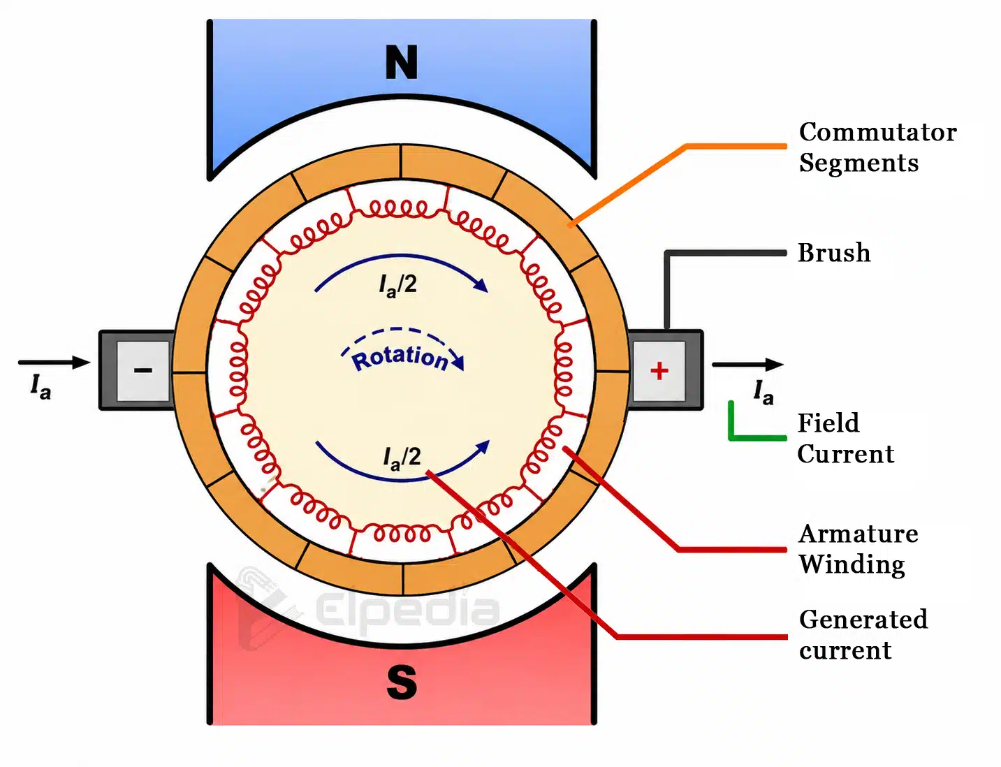
During the rotation of the armature, a coil carries current in one direction when the armature conductors are under the north (N) pole and in the opposite direction when they move under the south (S) pole. As the conductors move from the influence of the north pole to the south pole, the direction of current must reverse. This change occurs at the Magnetic Neutral Axis (MNA), also called the brush axis, where the brush briefly short-circuits the coil. During this short time, the current in the coil changes its direction. This process of reversing the current in the short-circuited coil is called commutation. The short interval during which the coil remains short-circuited is known as the commutation period (T).
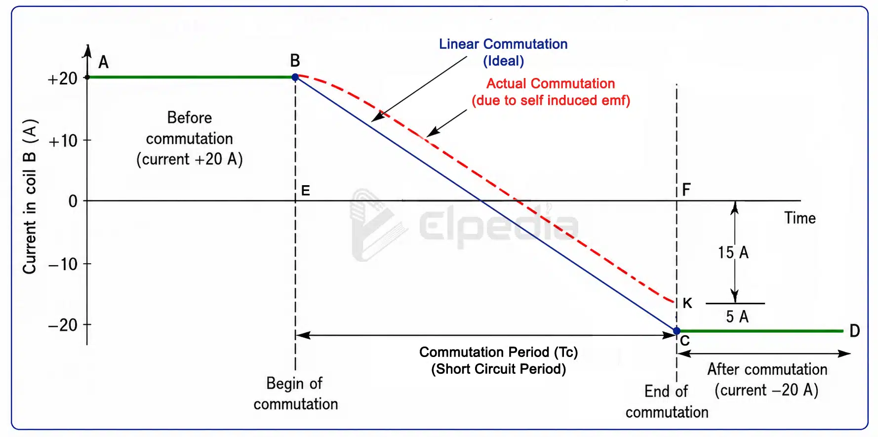
If the current changes completely from +I to 0 and then to −I within the short-circuit period, the commutation is called ideal commutation in dc machine. In this case, the current reversal is smooth and no sparking occurs. However, if the current does not fully reverse before the end of the commutation period, sparks are produced between the brush and the commutator. Continuous sparking can gradually damage both the brushes and the commutator, reducing the efficiency and life of the DC machine.
Good Commutation and Poor Commutation
Good commutation occurs when there is no sparking at the brushes, and the commutator surface remains smooth and undamaged during continuous operation of the DC machine.
Poor commutation occurs when sparking develops at the brushes, causing damage to the commutator surface. Sparking produces excessive heat at the contact point between the brush and the commutator and creates small pits on the commutator surface. As the surface becomes damaged, the electrical contact worsens, leading to even more heating and sparking. This cycle continues and gradually reduces the performance and lifespan of the machine. Therefore, for proper commutation in DC machine, the current in the coil must be completely reversed during the commutation period.
Poor commutation can result from mechanical or electrical causes. Mechanical causes include an uneven commutator surface, unequal brush pressure, and brush vibrations inside the holders. Electrical causes include a high voltage between adjacent commutator segments and excessive current density at the trailing edge of the brush. Both types of problems increase the chance of sparking and reduce the efficiency of the DC machine.
Process of Commutation in DC machine
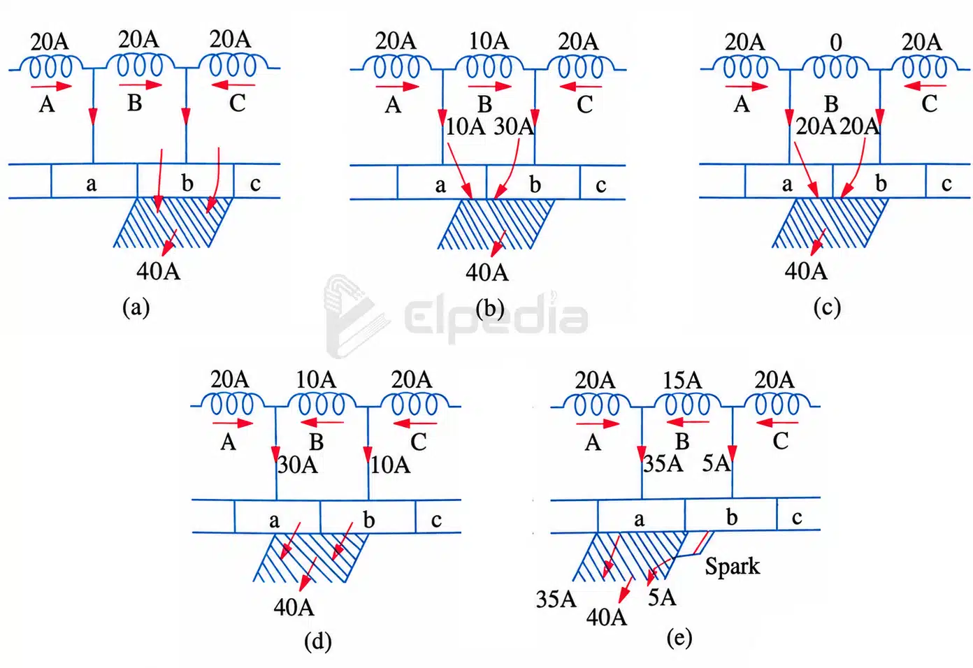
To understand the commutation in DC machine, consider a DC generator with a ring winding. Assume that the brush width is equal to the width of one commutator segment and one insulation gap (mica). Each armature coil carries 20 A, and the total current through the brush is 40 A.
Step 1: Before Commutation
Before the brush touches the next commutator segment as shown in above Fig(a), coil B carries 20 A of current in one direction. At this stage, it belongs to the group of coils on one side of the brush and supplies current normally.
Step 2: Beginning of Commutation
As the brush starts touching both commutator segments, coil B becomes short-circuited, as seen in above Fig(b). During this period, the current in the coil begins to decrease because part of the current now flows through the new commutator segment. The brush still carries a total current of 40 A, but the current is shared between the two segments.
Step 3: Middle of Commutation
When the brush makes equal contact with both commutator segments, the current in coil B becomes zero, as indicated in Fig(c). At this moment, the entire brush current is supplied by the neighboring coils. This is the point where the current in coil B changes its direction.
Step 4: Current Reversal
As the brush continues to move, its contact with the old segment decreases while contact with the new segment increases. The current in coil B now starts flowing in the opposite direction. The neighboring coils and coil B together continue to supply the required 40 A to the brush, which is shown in Fig(d).
Step 5: End of Commutation
By the time the brush leaves the old commutator segment, the current in coil B should have completely reversed to 20 A in the opposite direction, as shown in Fig(e). This condition is called ideal commutation. However, if the current has reversed only partially (for example, 15 A instead of 20 A), the remaining 5 A jumps across the air gap between the commutator segment and the brush, creating a spark.
If the current in the coil changes uniformly from +20 A to 0 and then to −20 A, the process is called linear commutation. In practice, the coil produces a self-induced emf that opposes the change in current. Because of this, the current does not reverse at a constant rate and follows a curved path instead of a straight line. As a result, the current may not reach its full reversed value before the commutation period ends. This is one of the main challenges in achieving ideal commutation in DC machine.
Reactance Voltage and Its Effect on Commutation
At this point, an important question arises: Why does the current not reverse completely during the commutation period? The main reason is the self-induced emf, also called reactance voltage, produced in the coil during commutation.
The armature coil has self-inductance because it is placed inside the magnetic core, which has high magnetic permeability. Whenever the current in the coil changes, the coil produces a self-induced EMF that opposes the change in current. This opposing voltage is called reactance voltage.
Although its value is small, the coil is short-circuited during commutation and has very low resistance. Therefore, even a small reactance voltage can produce a large opposing current, making it difficult for the current to reverse quickly.
Even when the brushes are placed exactly on the Magnetic Neutral Axis (MNA), where the rotating coil cuts no magnetic flux and no rotational EMF is induced, the self-induced EMF still exists. This reactance voltage delays the current reversal and can cause sparking between the brush and the commutator, making commutation in DC machine less effective.
The reactance voltage is given by the equation,
![\[V_r = L \frac{dI}{dt} \]](https://elpedia.com/wp-content/ql-cache/quicklatex.com-3b89c987cc7486d6b43f82a23dac3eec_l3.png "Rendered by QuickLaTeX.com")
During commutation in dc machine, the current changes from +I to −I, so the total change in current is dI = (+I) − (−I) = 2I.
The commutation period (or short-circuit period) is the time during which a coil remains short-circuited by the brush. It is equal to the time taken by the commutator to move a distance equal to the brush width minus the width of one insulating strip of mica.
If is the brush width in cm, is the width of mica insulation in cm and is the peripheral speed of the commutator in cm/sec, then the commutation period is given by,
![\[T_c = \frac{W_b - W_m}{v} \]](https://elpedia.com/wp-content/ql-cache/quicklatex.com-d8f2d8a458a37a3ab03a314058ea547a_l3.png "Rendered by QuickLaTeX.com")
The reactance voltage thus becomes,
![\[V_r = L \frac{2I}{T_c} \]](https://elpedia.com/wp-content/ql-cache/quicklatex.com-aaf63ff3f1f7a963d0e2485667a37d9e_l3.png "Rendered by QuickLaTeX.com")
Effect of Reactance Voltage
Reactance voltage opposes the reversal of current in the short-circuited coil. As a result, the current may not reach its full reversed value before the commutation period ends. This incomplete current reversal causes sparking at the brushes.
Continuous sparking damages both the brushes and the commutator surface. Over time, the damage increases, producing more sparking and overheating. In severe cases, the sparks may develop into a continuous electric arc between the brushes, which can lead to short-circuiting and failure of the entire DC machine.