Four point starter – Construction and Working
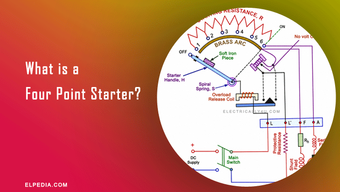
Four point starter is also a protective starting device similar to three point starter, used in DC shunt and compound motors. It safely starts the motor by limiting the high starting current and provides protection against low voltage and overload conditions.
In a three point starter, the no volt release coil is connected in series with the shunt field winding and the field rheostat. Because of this, the same current flows through both the shunt field and the no volt release coil.
When the field rheostat resistance is increased to control the motor speed, the field current decreases. Since the no volt release coil carries the same current, its magnetic pull also becomes weak. If the magnetic force is not strong enough to hold the starter handle, the spring pulls the handle back to the OFF position, stopping the motor.
This is a major disadvantage of the three point starter. For this reason, it is not suitable for speed-controlled DC shunt motors, and the four point starter is preferred.
Construction of four point starter
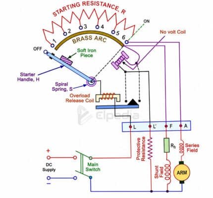
Similar to the three point starter, a four point starter consists of starting resistances divided into several sections, which are connected to the studs and brass arc.
It has 4 terminals named as L, L’, F and A. L terminal is connected directly to the positive supply, A terminal is connected to the armature winding and F terminal is connected to the shunt field winding.
In this starter, a new terminal L’ is connected to the no volt release coil directly across the negative supply through a protective resistor. It is not connected in series with the shunt field winding.
Similar to the three point starter, it has overload release coil connected to the starter handle H.
Working of a four point starter
When the starter handle touches the first stud, the supply current splits into three paths:
- One part flows through the starting resistance, armature, and series field winding.
- The second part flows through the shunt field winding.
- The third part flows through the no volt release coil and the protective resistance.
Since the no-volt release coil has its own separate circuit, changing the field current does not affect it. Even if the field rheostat is adjusted to change the motor speed, the no-volt release coil continues to receive enough current to produce a strong magnetic pull. This keeps the starter handle in the ON position and prevents the spring from pulling it back to OFF.
Because of this advantage, the four point starter is widely used for speed-controlled DC motors. The starting procedure for a four point starter is almost the same as that of a three point starter.
Before starting the motor, it is important to make sure that the field circuit is closed, the field rheostat is set to minimum resistance and the starting resistance connected to the armature is at its maximum value.
After the motor starts, the field rheostat can be adjusted to obtain the required speed above the normal speed.
To stop the motor, always open the main line switch instead of pulling the starter handle back to the OFF position.
In a DC shunt motor, the back EMF is almost equal to the supply voltage while the motor is running. Therefore, only a small voltage appears across the switch contacts, producing very little arcing when the line switch is opened.
If the starter handle is pulled back instead, the field circuit opens suddenly. Since the field winding is highly inductive, it produces a high voltage that creates a strong arc at the contacts. This can damage or burn the starter contacts.
Before switching off the motor, return the field rheostat to its minimum resistance position. This restores the motor to its normal field strength and normal speed and then open the main line switch.
Following this procedure ensures that the next time the motor starts, it has a strong magnetic field and produces a high starting torque.
Difference between three point starter and four point starter
| Three point starter | Four point starter |
|---|---|
| It has 3 terminals (L, F, A). | It has 4 terminals (L, L’, F, A). |
| No volt coil is connected in series with the shunt field winding. | No volt coil is connected directly across the supply through a separate terminal. |
| The current in no-volt coil depends on field current. | The current in no-volt coil independent of field current. |
| It is not suitable for wide speed control using field weakening. | It is suitable for wide speed control using field weakening. |
| When field current is reduced, the motor may disconnect accidently. | When field current is reduced, the motor will not disconnect. |
| It provides protection if the field circuit opens. | Does not provide protection against field circuit failure. |
| It is used where speed variation is not required. | It is used where a wide range of speed control is required. |
| It is less expensive. | It is slightly more expensive. |
| It is simpler but has limitations. | It is more reliable for variable-speed applications. |