Ohm’s Law: Definition, Formula, Applications and Examples
Ohm’s Law is one of the first equations you encounter in any electrical engineering or physics course, and for good reason. It captures the relationship between voltage, current, and resistance in a single, elegant formula that applies across countless real-world scenarios.
Whether you are sizing a resistor for an LED, troubleshooting a car stereo, or studying for an exam, this law gives you a reliable starting point.
In this Elpedia guide, we break down the definition, formula, applications, limitations, and worked examples of Ohm’s Law so you can apply it with confidence.
Key Takeaways
Ohm’s Law describes the relationship between voltage, current, and resistance in electrical circuits.
It is a fundamental principle that forms the backbone of basic circuit analysis for students, technicians, and electrical engineers alike.
- The core Ohm’s Law formula is V = I × R. Knowing any two values lets you calculate the third, making it indispensable for circuit theory.
- Combining Ohm’s Law with power equations (P = V × I, P = I²R, P = V²/R) lets you calculate electrical power and electrical energy used by devices such as a 60 W lamp or a 2 kW heater.
- Ohm’s Law applies mainly to ohmic, resistive circuits and has limitations for time varying AC signals with reactive components and for non-ohmic devices like diodes and filament lamps.
- This article includes worked numerical problems, series and parallel examples, common exam mistakes, and an FAQ, written from Elpedia’s perspective as an educational resource.
What is Ohm’s Law?
Ohm’s Law is one of the basic and most important laws in electrical engineering. It explains the relationship between voltage, current, and resistance in an electrical circuit.
According to Ohm’s Law, the current flowing through a conductor is directly proportional to the voltage applied across it, provided that the physical conditions, particularly temperature, remain constant. The relationship is expressed as,
![\[ V = I \times R \]](https://elpedia.com/wp-content/ql-cache/quicklatex.com-36e218be0c9ac773478c39d425a792ab_l3.png "Rendered by QuickLaTeX.com")
where V is the voltage across the conductor, measured in volts (V), I is the current flowing through the conductor, measured in amperes (A) and R is the resistance of the conductor, measured in ohms (Ω).
Consider a simple circuit containing a battery, lamp, and connecting wires. The battery provides the voltage needed to make current flow through the circuit. The lamp offers resistance to the flow of current. The amount of current flowing through the lamp depends on the supplied voltage and the resistance of the lamp.
For example, if a 12 V battery is connected to a lamp with a resistance of 6 Ω:
![\[I = \frac{V}{R} = \frac{12}{6} = 2\text{ A} \]](https://elpedia.com/wp-content/ql-cache/quicklatex.com-41db1d2b288cbfd6965977eda7e2740b_l3.png "Rendered by QuickLaTeX.com")
Therefore, the current flowing through the lamp is 2 A.
Ohm’s Law is empirical, meaning it was discovered experimentally rather than derived from first principles.
Modern theories explain it through electron motion, drift velocity, and the electric field inside conductors, but the practical formula remains unchanged.
Even though electrical circuits can become very complex, the basic relationship between voltage, current, and resistance remains an important starting point for understanding circuit behavior.
For beginners, Ohm’s Law is mainly used to understand resistive circuits. As students learn more about electrical engineering, the same basic concepts are extended to circuits containing components such as capacitors and inductors, whose behavior can change with time.
Historical Background and Georg Ohm
Georg Simon Ohm, a German physicist born in 1789 in Erlangen, Bavaria, is the scientist behind one of the most important laws used in electrical engineering.
During the early 19th century, the study of electricity was still developing. Scientists could observe electrical effects, but there was a need to understand these effects in a clear and mathematical way.
Ohm worked to find a mathematical relationship between the applied voltage and the current flowing through a conductor.
Georg Ohm published his findings in 1827 in his book Die galvanische Kette, mathematisch bearbeitet. Using primitive instruments, he measured current through wires of varying lengths and materials under different voltage supplies and found a consistent ratio that we now call resistance.
Ohm’s work was not immediately accepted. Some scientists criticized his mathematical approach and were more comfortable with qualitative descriptions of electrical phenomena.
However, his results were later verified by other scientists, including Gustav Theodor Fechner and Heinrich Lenz. By the 1850s, Ohm’s work had gained wide acceptance.
It is also worth noting that Henry Cavendish had performed experiments related to electrical resistance as early as 1781. However, he did not formally publish his results.
Ohm was therefore the scientist who clearly presented the quantitative relationship between voltage, current, and resistance.
In recognition of his contribution, the SI unit of electrical resistance was named the ohm (Ω) after Georg Ohm.
Today, Ohm’s Law remains one of the fundamental principles of electrical engineering. It is widely used in electronic circuits, electrical power systems, and circuit analysis.
For students learning electrical engineering, it provides one of the simplest ways to understand how voltage, current, and resistance are related.
Voltage, Current, and Resistance: Core Electrical Quantities
Ohm’s Law connects three quantities, voltage, current, and resistance, and understanding each is essential before applying the formula.
Voltage (V): The electrical potential difference between two points in a circuit. It is measured in volts (V). Voltage provides the push that causes electric charges to move through a circuit. It can be compared to water pressure in a pipe: higher pressure can produce a greater flow of water.
Common voltage sources include a 1.5 V AA battery, a 9 V cell, or 120/230 V mains from a power supply.
In simple terms, voltage is the push that drives current through a circuit.
Current (I): The rate at which electric charge flows through a circuit, measured in amperes (A). One ampere means that one coulomb of electric charge passes through a point in the circuit every second.
For example, a typical phone charger may supply around 1–3 A, depending on its design and charging mode.
In simple terms, current is the flow of electric charge.
Resistance (R): It is the opposition offered by a material or component to the flow of electric current. It is measured in ohms (Ω). Resistance depends on material, length, and cross-sectional area.
For example, copper has very low resistance, which is why it is widely used for electrical wires. A longer and thinner copper wire has more resistance than a shorter and thicker copper wire of the same material.
In simple terms, resistance opposes or limits the flow of current.
Qualitatively, think of how voltage acts as push, resistance as opposition, and current as the resulting flow. Ohm’s Law makes this relationship quantitative: doubling voltage doubles current if resistance stays the same; doubling resistance halves current for the same voltage.
For basic circuit analysis, we assume constant temperature and stable component properties so that resistance does not change during the calculation.
Ohm’s Law Formula and Triangle
The Ohm’s Law formula has three standard algebraic forms used in textbooks and exams:
Find | Formula |
|---|---|
Voltage | V = I × R |
Current | I = V ÷ R |
Resistance | R = V ÷ I |
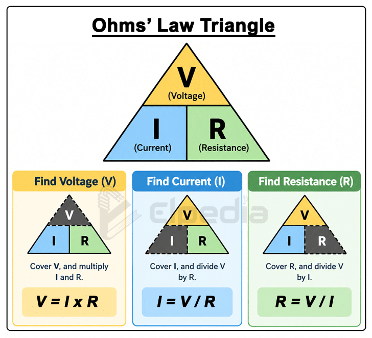
Voltage can be calculated as V = I × R, current can be calculated as I = V/R, and resistance can be calculated as R = V/I. Knowing any two values lets you find the third.
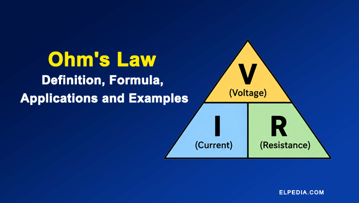
The Ohm’s Law Triangle is a simple visual aid that makes these three formulas easier to remember. The triangle has V (voltage) at the top and I (current) and R (resistance) at the bottom, as shown below.
To find a quantity, cover that quantity in the triangle:
- Cover V → you see I × R
- Cover I → you see V ÷ R.
- Cover R → you see V ÷ I.
Quick example:
If a circuit has a voltage of 12 V and a resistance of 6 Ω, the current is:
![\[I = \frac{V}{R} = \frac{12}{6} = 2 A \]](https://elpedia.com/wp-content/ql-cache/quicklatex.com-2de6045da1ddc5a035667aeb765b31e2_l3.png "Rendered by QuickLaTeX.com")
The Ohm’s Law Triangle is particularly useful for beginners and students preparing for examinations because it provides a quick way to recall and rearrange the three basic forms of Ohm’s Law.
For a broader understanding of electrical power relationships, you can also study the power triangle and the Ohm’s Law wheel, which combines Ohm’s Law equations with power formulas in a single visual chart.
How Ohm’s Law Works – Intuitive Analogy
Think of water flow through a plumbing system. A pump raises water pressure (analogous to voltage), water flows through pipes (analogous to conductors), and a narrow section or valve restricts the flow (analogous to resistance). The amount of water passing through per second is the current.
- Water pressure difference = voltage (driving voltage that pushes flow).
- Water flow rate = electrical current.
- Pipe narrowing or valve = resistance.
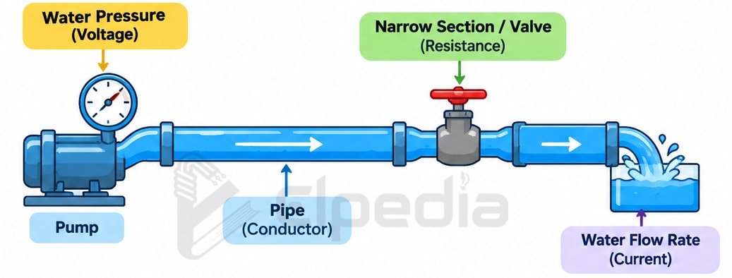
Increasing pressure (voltage) raises flow (current) if pipe size (resistance) stays the same, mirroring how current is directly proportional to voltage. Narrowing the pipe (increasing resistance) reduces flow for the same pressure, matching I = V / R.
The analogy has its limitations. Electrons are not water molecules, and AC circuits involve phase and frequency effects that cannot be fully represented by a simple pipe model.
However, for understanding how voltage and resistance affect current in a basic DC circuit, the hydraulic analogy is a useful and intuitive way to visualize the relationship.
V–I Characteristics of Ohmic Conductors
A V–I (voltage–current) characteristic graph plots voltage on the vertical axis and current on the horizontal axis. It is a standard tool in circuit analysis for determining whether a device obeys Ohm’s Law.
- An ohmic device, such as a metallic resistor, produces a straight-line V–I characteristic that passes through the origin. The slope of the V–I graph represents the resistance.
- For an ohmic conductor, doubling the applied voltage approximately doubles the current. This indicates that the resistance remains constant and the device exhibits linear behavior.
- Non-ohmic devices, such as diodes and incandescent lamps, produce curved V–I characteristics because their resistance changes with factors such as temperature, current, or applied voltage.
Numerical example: Consider a 10 Ω resistor tested at 5 V, 10 V, and 15 V. Using Ohm’s Law, the corresponding currents are 0.5 A, 1.0 A, and 1.5 A, respectively. These points lie on a straight line passing through the origin, confirming that the resistor behaves as an ohmic device under these normal operating conditions.
Ohmic and Non-Ohmic Devices
An ohmic device is a component that obeys Ohm’s Law over a specified operating range, with its resistance remaining approximately constant.
Examples of ohmic devices: Fixed metal-film resistors, carbon resistors, metallic heating elements operating at a stable temperature, and other simple resistive loads under suitable operating conditions.
Non-ohmic devices, on the other hand, do not maintain a constant resistance. Their resistance may vary significantly with voltage, current, temperature, or the direction of current flow. As a result, they produce a curved V–I characteristic rather than a straight line.
For example, a typical filament lamp may have a resistance of about 20 Ω when cold and around 200 Ω when operating at a high temperature.
Examples of non-ohmic devices: Semiconductor diodes, LEDs, transistor junctions, filament lamps, thermistors, varistors, and electrolytic cells.
In advanced circuit analysis, a non-ohmic device can be described at a particular operating point using dynamic (or differential) resistance, defined as the local slope of the V–I characteristic,
![\[r_d = \frac{dV}{dI} \]](https://elpedia.com/wp-content/ql-cache/quicklatex.com-ac7d049156586536ff95df9715d97fd4_l3.png "Rendered by QuickLaTeX.com")
This concept is useful for analyzing the small-signal behavior of nonlinear devices, but it is beyond the basic application of Ohm’s Law.
Ohm’s Law in Series and Parallel Circuits
Most practical electrical circuits contain multiple components. In such circuits, Ohm’s Law is used together with the rules for series and parallel circuits to determine voltage, current, and resistance.
Series circuits:
- The total resistance is the sum of all individual resistances.
- The same current flows through every component.
- The supply voltage is divided among the components according to their resistances.
- The voltage drop across each resistor can be calculated using Ohm’s Law.
- For example, consider two resistors of 4 Ω and 6 Ω connected in series across a 12 V supply.
![\[ R_{\text{total}} = 4 + 6 = 10\ \Omega \]](https://elpedia.com/wp-content/ql-cache/quicklatex.com-ada3cd9c5de47ef3a37fef49ffdbee84_l3.png "Rendered by QuickLaTeX.com")
![\[I = \frac{V}{R_{\text{total}}} = \frac{12}{10} = 1.2\text{ A} \]](https://elpedia.com/wp-content/ql-cache/quicklatex.com-cec371ecd738ac073d6867a9ab99e2e2_l3.png "Rendered by QuickLaTeX.com")
- Therefore, the voltage drops across the 4 Ω resistor can be calculated using the ohm’s law V1 = I x R1 = 1.2 x 4 = 4.8 V and across the 6 Ω resistor, it will be V2 = I x R2 = 1.2 x 6 = 7.2 V.
Parallel circuits:
- The reciprocal of the equivalent resistance is equal to the sum of the reciprocals of the individual branch resistances.
- The same voltage appears across every branch.
- The total current is divided among the branches according to their resistances.
- Ohm’s Law can be applied separately to each branch to determine its current.
- For example, consider 10 Ω and 20 Ω resistors connected in parallel across a 12 V supply.
![\[ \frac{1}{R_{\text{eq}}} = \frac{1}{10} + \frac{1}{20} \]](https://elpedia.com/wp-content/ql-cache/quicklatex.com-e926c0f8483dbfe95d7c13dc726a9878_l3.png "Rendered by QuickLaTeX.com")
![\[ R_{\text{eq}} = 6.67\ \Omega \]](https://elpedia.com/wp-content/ql-cache/quicklatex.com-b6030e75f9a2dcd66d8c5bf32281efae_l3.png "Rendered by QuickLaTeX.com")
- The total current is,
![\[ I_{\text{total}} = \frac{V}{R_{\text{eq}}} = \frac{12}{6.67} =1.80\text{ A} \]](https://elpedia.com/wp-content/ql-cache/quicklatex.com-6bc69a6baa156a88334aad7e4acbe46b_l3.png "Rendered by QuickLaTeX.com")
- Since the voltage across each branch is 12 V, the branch currents through the 10 Ω resistor and 20 Ω resistor is
![\[I_1 = \frac{V}{R_1} = \frac{12}{10} = 1.2\text{ A} \]](https://elpedia.com/wp-content/ql-cache/quicklatex.com-085ad06a6875dd6c67b1263ba9b79157_l3.png "Rendered by QuickLaTeX.com")
![\[ I_2 = \frac{V}{R_2} = \frac{12}{20} = 0.6\text{ A} \]](https://elpedia.com/wp-content/ql-cache/quicklatex.com-e2c90d4fd1f649f1d47969f7157cff3b_l3.png "Rendered by QuickLaTeX.com")
Use the Series and Parallel Resistance Calculator on Elpedia to verify your hand calculations quickly.
These principles show how Ohm’s Law is applied to individual components or branches after determining the equivalent resistance, branch voltages, or branch currents.
They also form the foundation for more advanced circuit-analysis techniques, where Ohm’s Law is combined with Kirchhoff’s Current Law (KCL) and Kirchhoff’s Voltage Law (KVL).
Ohm’s Law and Electrical Power
Electrical power (P) is the rate at which electrical energy is converted to other forms such as heat, light, or kinetic energy, measured in watts (W).
The primary formula for power is P = V × I. Substituting Ohm’s Law equations produces two useful variants:
Known Values | Power Formula |
|---|---|
Current and resistance | P = I² × R |
Voltage and resistance | P = V² / R |
These three equations are different forms of the same power relationship and can be selected depending on the known values in a circuit.
Power calculations are important for component selection and circuit design. They help ensure that resistors, wires, and other components can safely handle the power they dissipate without excessive heating or damage.
Example: A 12 V car lamp draws a current of 2 A. Its electrical power consumption is:
![\[P = V\times I = 12 \times 2 = 24\text{ W} \]](https://elpedia.com/wp-content/ql-cache/quicklatex.com-883d0b364513acdf43bda2ad623f3e3a_l3.png "Rendered by QuickLaTeX.com")
If the lamp operates continuously for one hour, the electrical energy transferred is:
![\[E = P \times t = 24 \times 1 = 24\text{ Wh} \]](https://elpedia.com/wp-content/ql-cache/quicklatex.com-20ba0ee35ae16811fa8039003a7b0c58_l3.png "Rendered by QuickLaTeX.com")
Understanding electrical power is essential when selecting components, from a 0.25 W signal resistor to a 50 W power resistor.
It also helps in understanding appliance ratings—for example, a 100 W bulb consumes power at a much lower rate than a 2000 W electric kettle.
Numerical Problems on Ohm’s Law
This section presents step-by-step worked examples using realistic values from everyday electric circuits.
Problem 1 – Finding Current: A 24 V battery is connected across an 8 Ω resistor. Find the current flowing through the resistor.
Using Ohm’s Law,
![\[I = \frac{V}{R} = \frac{24}{8}\]](https://elpedia.com/wp-content/ql-cache/quicklatex.com-05820ed854f58a9bf9b0f4d16e89a40a_l3.png "Rendered by QuickLaTeX.com")
![\[I = 3 \, A} \]](https://elpedia.com/wp-content/ql-cache/quicklatex.com-5fe28ec1452ab1363d21f09f58ff2293_l3.png "Rendered by QuickLaTeX.com")
Problem 2 – Calculating Resistance: A device draws a current of 2.5 A when a voltage of 15 V is applied across it. Find its resistance.
Using Ohm’s Law,
![\[ R = \frac{V}{I} =\frac{15}{2.5} \]](https://elpedia.com/wp-content/ql-cache/quicklatex.com-9df13497ec693a9248365d8222abe46e_l3.png "Rendered by QuickLaTeX.com")
![\[R = 6\, \Omega} \]](https://elpedia.com/wp-content/ql-cache/quicklatex.com-95c054fc6610002254ff876b9bda33de_l3.png "Rendered by QuickLaTeX.com")
Problem 3 – Power Dissipated: A 10 Ω resistor is connected to a 20 V supply. Find the power dissipated by the resistor.
Using the power equation,
![\[P = \frac{V^2}{R} \]](https://elpedia.com/wp-content/ql-cache/quicklatex.com-a7ac28c500848d24d178f5d8f921bb95_l3.png "Rendered by QuickLaTeX.com")
![\[P = \frac{20^2}{10} = \frac{400}{10} \]](https://elpedia.com/wp-content/ql-cache/quicklatex.com-c96f5328ab0e8077be856b55222f1829_l3.png "Rendered by QuickLaTeX.com")
![\[P = 40\, W \]](https://elpedia.com/wp-content/ql-cache/quicklatex.com-ed5b33358976fefd6bab7b19587914f8_l3.png "Rendered by QuickLaTeX.com")
You can cross-check the answer:
First, calculate the current:
![\[ I = \frac{V}{R} = \frac{20}{10} = 2\text{ A} \]](https://elpedia.com/wp-content/ql-cache/quicklatex.com-3b516861f389d9e7c187a6a17564d852_l3.png "Rendered by QuickLaTeX.com")
![\[\text{Then, }P = I^2R = 2^2 \times 10 \]](https://elpedia.com/wp-content/ql-cache/quicklatex.com-a9796e13466e04b93a35513140f364fe_l3.png "Rendered by QuickLaTeX.com")
![\[P= 40\text{ W} \]](https://elpedia.com/wp-content/ql-cache/quicklatex.com-2f876ed3c7599fb431f87cb13b52c874_l3.png "Rendered by QuickLaTeX.com")
The result is the same, confirming the calculation. ✓
Problem 4 – Series Circuit: Two resistors of 3 Ω and 6 Ω are connected in series across a 9 V battery. Find the circuit current and the voltage drop across each resistor.
The total resistance is,
![\[R_{\text{total}} = 3 + 6 = 9\ \Omega \]](https://elpedia.com/wp-content/ql-cache/quicklatex.com-345547e312b51a38af2864cd69f3dfae_l3.png "Rendered by QuickLaTeX.com")
The circuit current is,
![\[I = \frac{V}{R_{\text{total}}} = \frac{9}{9} \]](https://elpedia.com/wp-content/ql-cache/quicklatex.com-b35b18fe1b20a5adb0ce823717af43b2_l3.png "Rendered by QuickLaTeX.com")
![\[I = 1\, A\]](https://elpedia.com/wp-content/ql-cache/quicklatex.com-f64330d9e058125013c0340a8fece21f_l3.png "Rendered by QuickLaTeX.com")
Since the same current flows through both resistors, voltage drop across the 3 Ω resistor and 6 Ω resistor are calculated as,
![\[V_1 = IR_1 = 1 \times 3 = 3\, V \]](https://elpedia.com/wp-content/ql-cache/quicklatex.com-28ba30d58c3e03d6af5c1a88c4da6c7b_l3.png "Rendered by QuickLaTeX.com")
![\[V_2 = IR_2 = 1 \times 6 = 6\, V\]](https://elpedia.com/wp-content/ql-cache/quicklatex.com-2881696e9cc04a221fc3b2cdeaa19d2b_l3.png "Rendered by QuickLaTeX.com")
You can cross-check the answer:
![\[V_1 + V_2 = 3 + 6 = 9\text{ V} \]](https://elpedia.com/wp-content/ql-cache/quicklatex.com-3b0d3651d5b33ab57814d6213e6c6afc_l3.png "Rendered by QuickLaTeX.com")
The sum of the voltage drops equals the supply voltage. ✓
Problem 5 – LED Resistor Selection: An LED requires a forward voltage of 2 V and a current of 20 mA. It is connected to a constant 5 V supply. Find the required series resistor to limit the LED current.
The resistor must drop the remaining voltage,
![\[V_R = 5 - 2 = 3\text{ V} \]](https://elpedia.com/wp-content/ql-cache/quicklatex.com-34fe17ceb8c919f6eb86d6baf6f24e79_l3.png "Rendered by QuickLaTeX.com")
Using Ohm’s Law,
![\[R = \frac{V_R}{I}\]](https://elpedia.com/wp-content/ql-cache/quicklatex.com-b045be3fdbbeb43b64dfe9f3e6de8caf_l3.png "Rendered by QuickLaTeX.com")
![\[R = \frac{3}{0.020} = 150\, \Omega\]](https://elpedia.com/wp-content/ql-cache/quicklatex.com-2cf1b0220b8904ad3c985fb6de6e7a68_l3.png "Rendered by QuickLaTeX.com")
Ohm’s Law in Time-Varying (AC) and Resistive Circuits
In a purely resistive circuit, Ohm’s Law applies even when the voltage and current vary with time, such as in a sinusoidal AC circuit operating at 50 Hz or 60 Hz. For an ideal resistor, the instantaneous voltage and current are always proportional:
![\[v(t) = i(t) \times R \]](https://elpedia.com/wp-content/ql-cache/quicklatex.com-ebdb5e3866cd3c32106dd4d2f79f7a49_l3.png "Rendered by QuickLaTeX.com")
The voltage and current waveforms are in phase, meaning there is zero phase difference between them. Consequently, the V–I characteristic remains a straight line, just as it does for a DC resistive circuit.
In AC circuits containing inductors and capacitors, the relationship between voltage and current is generalized using impedance (Z):
![\[V = I\times Z \]](https://elpedia.com/wp-content/ql-cache/quicklatex.com-0bf3ba85c5b38a908a499aa1bf78891f_l3.png "Rendered by QuickLaTeX.com")
For a purely resistive element, however, impedance is equal to resistance, so the usual Ohm’s Law relationship can be used. The familiar power equations can also be applied using RMS values of voltage and current.
Example : Consider a 100 W incandescent lamp rated at 220 V RMS. Assuming its operating resistance is approximately constant at its rated operating condition:
![\[R = \frac{V^2}{P} = \frac{220^2}{100} = 484\ \Omega \]](https://elpedia.com/wp-content/ql-cache/quicklatex.com-81e92b695bef3360fde3fd76c6fec509_l3.png "Rendered by QuickLaTeX.com")
The RMS current will be,
![\[I = \frac{V}{R} = \frac{220}{484} = 0.455\text{ A} \]](https://elpedia.com/wp-content/ql-cache/quicklatex.com-eb8eff6e62dc45b077cb9fa864088e8c_l3.png "Rendered by QuickLaTeX.com")
Thus, the lamp consumes approximately 100 W of average power under its rated operating conditions.
Although the instantaneous voltage and current vary continuously in an AC circuit, the use of RMS quantities allows the familiar power relationship to be applied conveniently to a resistive load.
Non-linear or reactive behavior (filters, motors) requires more advanced analysis in AC circuits, which Elpedia covers in dedicated guides on phasor diagrams and impedance.
Applications of Ohm’s Law
Electrical engineers use Ohm’s Law regularly in circuit design, analysis, safety assessment, and troubleshooting. It is applicable to a wide range of systems, from residential wiring and automotive electronics to industrial automation.
- Design: Choosing resistor values to set LED currents, designing voltage dividers for sensors, and verifying supply currents for microcontroller boards. Understanding other values like cross section of wires helps the engineers to set appropriate resistance values in power distribution.
- Safety: Engineers apply Ohm’s Law for circuit safety and performance evaluations. Using I = V / R to estimate fault currents helps them in selecting proper fuses and circuit breakers. A high voltage source across a very low resistance can produce dangerous current levels.
- Troubleshooting: Technicians use Ohm’s Law to validate circuit behavior and diagnose issues. By comparing measured values from a multimeter (you can measure voltage in parallel and current in series) with predicted values, they can identify short circuits, open circuits, or damaged components. Ohm’s Law helps diagnose circuit issues without dismantling components, and it is essential for calculating resistance in live circuits.
- Energy and cost: Ohm’s Law, together with the electrical power and energy relationships (P = VI) and (E = Pt), can be used to estimate energy consumption and operating costs. A 1500 W heater used for 2 hours consumes 3 kWh. At
 0.36.
0.36.
 0.36.
0.36.Limitations of Ohm’s Law
Ohm’s Law is powerful, but it is not universal. It has specific conditions for validity, especially constant temperature and linear, ohmic behavior.
- It does not accurately describe circuits where resistance changes significantly with temperature (e.g., incandescent bulbs), electric field strength, or current level.
- It does not directly apply to non-ohmic components such as diodes, transistors, vacuum tubes, and many semiconductor devices where the V–I relationship is exponential.
- At high frequencies or in systems with significant time-varying electric and magnetic fields, a simple resistance model may not be sufficient. The circuit may need to be analyzed using impedance, distributed parameters, or transmission-line models.
- For electrolytic solutions, gas discharge tubes, and arc lamps, experimental V–I curves deviate strongly from a straight line, requiring different empirical laws.
- In superconductors, resistance drops to zero, so the law cannot predict currents without considering other limiting factors.
Common Mistakes When Using Ohm’s Law
Many beginners make predictable errors that can be avoided with careful attention to units and circuit conditions.
- Unit mix-ups: Mixing volts with millivolts, amps with milliamps, or ohms with kilo-ohms without converting properly leads to errors by factors of 1000 or more.
- Wrong topology: Misidentifying series vs. parallel connections and therefore using the wrong equivalent resistance formula before applying Ohm’s Law.
- Ignoring power ratings: Calculating current correctly but forgetting to check P = I²R or P = V²/R to ensure resistors or wires do not overheat. Power calculations using Ohm’s Law are not optional-they are a safety check.
- Applying to non-ohmic devices: Using R = V / I for a diode at one operating point and assuming that “resistance” applies at all voltages is a common trap.
- Confusing peak and RMS in AC: Using peak values when RMS values are needed (or vice versa) can double or halve your calculated power.
Always sketch a simple circuit diagram and note known quantities before plugging into formulas. This single habit prevents most errors.
Key Points to Remember
- Ohm’s Law states V = I × R. The three rearrangements (V = IR, I = V/R, R = V/I) let you solve for any unknown when two values are given.
- Power formulas P = VI, P = I²R, and P = V²/R are direct extensions and are essential for thermal and energy analysis.
- Ohm’s Law applies well to linear, resistive circuits. Ohmic devices have straight-line V–I characteristics; non-ohmic devices do not.
- Always use consistent SI units and prefixes (V, A, Ω, W, J, kWh) in all calculations. A single prefix error can produce absurd results.
- While Ohm’s Law is simple, it is central to more advanced topics such as circuit analysis, AC systems, and electronic design. Explore Elpedia’s basic electrical engineering definitions and dedicated guides on source transformation to build on these foundations.
Frequently Asked Questions
Below are answers to common, practical questions that go beyond the main explanations above.