Three point starter – Construction & Working
A three point starter is a protective starting device used with DC shunt motors and compound motors to limit the high starting current and protect the motor from damage. Since the armature resistance of a DC motor is very low, connecting the motor directly to the power supply at the time of starting will draw a dangerously high current.
To solve this problem dc motor starter is used, which inserts resistance in series with the armature circuit that will protect the motor during starting.
In this article, you will learn the construction and working principle of a three point starter, and why it is replaced by the four point starter in variable-speed applications.
Construction of three point starter
The three point starter diagram shown below illustrates the internal construction and electrical connections of a three point starter used with DC shunt and compound motor.
It consists of starting resistances integrated into several sections. The contact points of these sections are connected to brass studs (numbered from 1 to 6) and brass arc. It has three main terminals L, F, and A, and so called three point starter.
In this, L represent the line terminal, which is connected to the positive terminal of the DC power supply. A represent the armature terminal, which is connected to the armature winding of the motor. F represent the field terminal, which is connected to the field winding of the motor.
The negative terminal of the DC supply is connected directly to both armature terminal and field terminal, which are joined together.
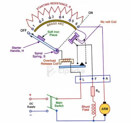
Inside the starter, the line terminal (L) is connected to an electromagnet called the overload release coil. The other end of this coil is connected to the starter handle (H). The starter handle carries a soft iron piece and can be moved manually from the OFF position to the ON position.
A spring is placed over the starter handle. While moving the handle, the spring gets stretched. If the handle is released or a fault occurs, the spring automatically pulls it back to the OFF position, disconnecting the motor from the power supply.
Another connection is taken from the far end of the brass arc to the no-voltage release coil, which is connected in series with the field winding through the field (F) terminal.
The overload release coil and the no-voltage coil are the two important protective devices in a three-point starter. The overload release coil protects the motor from excessive current, while the no-volt release coil protects it from low-voltage or power failure conditions.
Working of a three point starter
When the DC motor is at rest, the starter handle stays in the OFF position because a strong spiral spring pulls it back.
To start the motor, first switch on the DC power supply while keeping the starter handle in the OFF position. Then slowly move the starter handle clockwise to the first stud.
As soon as the handle touches the first stud, the entire starting resistance (Rs) is connected in series with the armature and the shunt field winding is connected directly across the supply through the brass arc which will energize the no-volt release coil.
The starting current drawn by the armature will be,
![\[ I_a = \frac{V}{R_a + R_s} \]](https://elpedia.com/wp-content/ql-cache/quicklatex.com-b8fb15e9cb3ce45d9b324fbbdcb80c28_l3.png "Rendered by QuickLaTeX.com")
As the handle is moved from one stud to the next, the starting resistance is gradually removed from the armature circuit. This limits the starting current while the motor gains speed.
When the handle reaches the ON position, all the starting resistance is removed from the circuit. The energized no-volt release coil creates a magnetic force that holds the handle in the ON position against the pull of the spring.
No-Volt Release coil – When the starter handle reaches the ON position, the motor runs at its normal speed because the starting resistance has been completely removed.
Now consider, if the power supply suddenly fails or is switched off, the starter handle would normally remain in the ON position. If the power returns while the handle is still in this position, the armature would be connected directly across the supply without any starting resistance. Since there is no back EMF at the moment of restarting, the motor would draw a very large current, which could damage the armature.
To prevent this problem, a no-volt release coil is used.
The no-volt release coil is an electromagnet connected in series with the shunt field winding. When the motor is operating normally, the coil remains energized and holds the starter handle in the ON position.
If the supply voltage fails or the shunt field circuit becomes open, the no-volt release coil loses its magnetism. As a result, it can no longer hold the starter handle. The spring immediately pulls the handle back to the OFF position, disconnecting the motor from the power supply.
Another important function of the no-volt release coil is to protect the motor if the shunt field circuit becomes open. In this condition, the coil is de-energized, allowing the spring to return the starter handle to the OFF position. This disconnects the motor from the supply and prevents the motor from running at a dangerously high speed.
Overload Release Coil – This coil is used to protect the motor from excessive current caused by overload. This coil is connected in series with the motor armature, so it carries the full motor current during normal operation.
When the motor is overloaded, the armature current increases. This higher current also flows through this coil, making it strongly magnetized.
The magnetic force of the coil pulls its armature plate, which short-circuits the no- volt release coil. Once it is short-circuited, it loses its magnetic force and can no longer hold the starter handle.
The spiral spring then pulls the starter handle back to the OFF position, disconnecting the motor from the power supply automatically. This protects the motor from overheating and damage due to excessive current.
For DC motors up to 15 kW, the overload release is usually built into the starter. In olden days, the dc motor starters are operated manually, in which the overload protection is less accurate and less reliable, hence they are rarely used these days. Modern motor control systems usually use circuit breakers with adjustable trip settings, magnetic contactors with overload relays, or thermal overload relays.
In a thermal overload relay, a bimetallic strip is heated by the motor current. If the motor overheats due to prolonged overload, the strip bends and trips the relay. This opens the contactor and disconnects the motor from the supply, preventing damage.
Limitation of three point starter
The main drawback of a three point starter appears during field control speed regulation.
When the field rheostat is adjusted to increase speed, the field current decreases. If it becomes too low, the hold-on coil does not produce enough magnetic force to hold the starter handle in the ON position.
As a result, the spring pulls the handle back to the OFF position and so the motor stops even though there is no fault.
Because of this limitation, the three point starter is not suitable for motors that require frequent or wide range of speed control. This problem led to the development of the four point starter, where the hold-on coil is connected directly across the supply instead of in series with the field winding. This allows the motor speed to be controlled without affecting the operation of the hold-on coil.