Speed Control of DC motor – Types and applications

Speed control of DC motor is the process of varying the rotational speed of a DC motor according to load requirements without affecting its performance. Because the speed of a DC motor can be controlled over a wide range, DC motors are extensively used in many adjustable speed drives such as electric traction, cranes, elevators, rolling mills, conveyors, machine tools, paper mills, and printing presses.
The different mechanisms of speed control can be deduced from the speed equation of a DC motor.
![\[N = \frac{V - I_aR_a}{\phi Z }\frac{P}{A} = K \frac{V - I_aR_a}{\phi } --->(1) \]](https://elpedia.com/wp-content/ql-cache/quicklatex.com-536a5060e620fdf8956b961650ee7d76_l3.png "Rendered by QuickLaTeX.com")
From the above expression, it is revealed that the speed of a dc motor depends on the following three factors.
- by varying the field current and hence flux per pole φ
- by varying the armature resistance, Ra and so the armature voltage
- supplying different voltage V
Therefore, the speed control of DC motor can be achieved by varying any one of these quantities while keeping the remaining parameters constant. Let us discuss, how the speed can be controlled with the above parameters.
Speed Control of DC Shunt motor
The speed control of DC shunt motor is comparatively simple because the field winding is connected in parallel with the armature circuit. This allows the field current and armature voltage to be controlled independently.
The commonly used methods of speed control of DC shunt motor are:
- Flux Control Method
- Armature Resistance Control Method
- Armature Voltage Control Method
- Ward Leonard System
Each method offers different speed ranges, efficiencies, and applications.
Flux control method
The flux control method, also known as the field control method, is one of the most efficient methods of speed control of DC motor.
From equation (1), it can be observed that,
![\[N \propto \frac{1}{\phi} \]](https://elpedia.com/wp-content/ql-cache/quicklatex.com-6215a89c644be38c2486f6a3ba366a84_l3.png "Rendered by QuickLaTeX.com")
By decreasing the flux produced by the field winding, the speed can be increased and vice versa. Hence the name flux control method or field control method.
The flux can be varied by varying the current Ish through the shunt field winding. It is done by connecting a rheostat in series with the field winding as shown below.
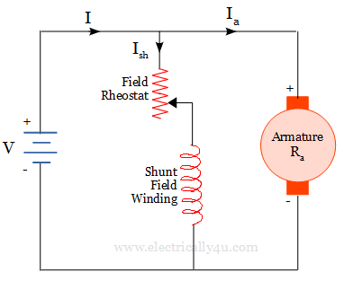
The shunt field current is relatively small, the field rheostat has to carry a very small current and hence I2R loss is so small. It is an efficient method of controlling the speed of a DC shunt motor. Using this method, speeds above the no-load speed can be achieved.
Because this method weakens the magnetic field, it is also called the field weakening method.
Armature control method
The armature resistance control method is one of the simplest methods of speed control of DC motor. In this method, additional resistance is added in series with the armature winding by using a rheostat. Since the current through armature is controlled with the rheostat, it is called an armature control method.
The speed can be reduced to any desired value depending on the amount of resistance added. The voltage across the armature drops as the current passes through the rheostat.
In proportion to the reduced voltage, the speed is reduced. However, the field current remains the same as the field winding is directly connected across the supply voltage.
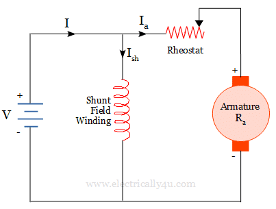
The armature control method is used where speed below the no-load speed is required. It also has poor speed regulation and low efficiency.
It provides an excellent starting characteristic by increasing the voltage gradually up from zero. Because of its advantage, it is used for printing machines, cranes, hoists, fans and blower applications.
Multiple Voltage Control
In this method, the field winding is excited by a constant voltage but the armature winding is supplied with different voltages through switching devices. The speed of the motor will be proportional to the armature voltage.
Using the switching devices, the armature voltage is increased or decreased. With respect to the change in voltage, the speed varies. This method of controlling the speed is not much adopted in real applications.
Unlike the armature resistance control method, this method does not waste power in an external rheostat. Therefore, it offers higher efficiency and better speed regulation, making it more suitable for applications that require frequent or continuous DC motor speed control.
In older DC drive systems, multiple voltage levels were obtained using tapped power supplies or motor-generator sets. However, modern day DC motor speed control systems use electronic converters such as controlled rectifiers, DC choppers, and thyristor-based drives to provide a variable armature voltage with high efficiency and precise speed control.
Ward Leonard System
The Ward Leonard system is one of the most accurate and reliable methods of speed control of DC motor. It is widely used in applications where precise, smooth, and continuous DC motor speed control is required over a wide speed range. This method controls the speed of the motor by varying the armature voltage while maintaining a constant field flux.
The following figure shows the arrangement of the Ward Leonard system. It consists of three machines, motor(M1), generator(G) and the main motor(M2) whose speed is to be controlled. The motor(M1) and Generator(G) sets are mechanically coupled with each other.
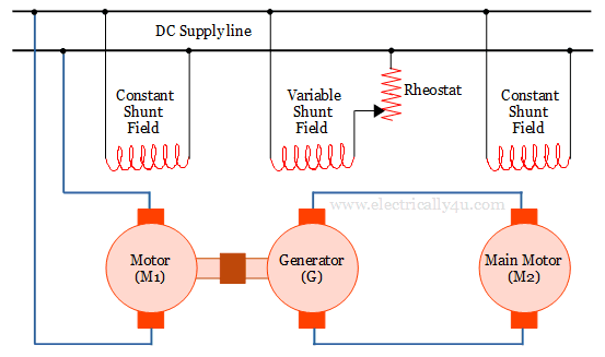
The prime mover (M₁) drives the DC generator (G) at a constant speed. By varying the field current of the generator, the generated output voltage can be changed smoothly from zero to its rated value. This variable DC voltage is supplied to the armature of the main DC motor (M₂).
According to the speed equation of DC motor, when the field flux remains constant, the motor speed is directly proportional to the armature voltage. Therefore, increasing the generator output voltage increases the speed of the main motor, while decreasing the voltage reduces its speed. This enables smooth, stepless, and precise speed control over a wide operating range.
The main disadvantage of ward leonard system is that the overall efficiency of the system is very low at light loads. But very fine speed control, uniform acceleration and good speed controls are possible with the system.
Ward Leonard system of speed control is used in applications such as steel rolling mills, paper machines, elevators, cranes, hoists, etc.,
Speed Control of DC Series motor
The speed control of DC series motor differs from that of a shunt motor because the field winding is connected in series with the armature winding. As a result, both the armature current and the field current are the same, making the magnetic flux dependent on the load current. Therefore, the speed control of DC series motor is achieved by varying either the field flux or the armature voltage.
Based on the speed equation of DC motor, the commonly used methods of speed control of DC series motor are classified into:
- Flux control methods
- Armature control methods
Each method provides different speed characteristics and is selected according to the application requirements.
Flux control method
In a DC series motor, the flux can be varied in different ways like diverting the field current, tapping the field current at different points in the field winding and paralleling the field coils. Let us discuss them in detail.
Field diverter method
A variable resistance (Rheostat) called field diverter is connected across the series field winding. A portion of the current flowing through the series field winding is diverted into the field diverter by varying its resistance.
It is illustrated in the figure below. By diverting the current, the flux produced is reduced. Hence the speed can be increased above the normal speed.
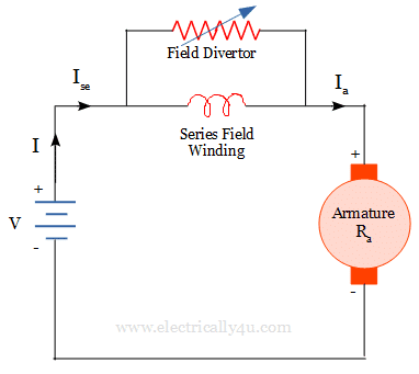
The lesser the diverter resistance, the more current will flow through the diverter, thereby the field current reduces and so the flux be produced. A decrease in flux will cause the motor speed to increase.
This method of speed control is used in electric drive applications, where a sharp increase in speed is needed.
Tapped Field control method
The speed can be controlled by varying the number of turns in the field winding. This is achieved by tapping out the series field winding at several points, as shown in the figure below.
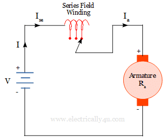
When the entire field is connected, the motor runs at the lowest speed. The speed can be further increased in steps by cutting out the resistance in the series turns. This method of speed control is used in electric traction.
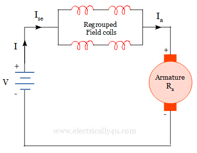
Paralleling field coils method
The field coils can be paralleled with additional winding to obtain the required speed. It can also be done by regrouping the field coils in the motor, as shown below.
By regrouping the field coils the resistance in the field winding can be varied, which will give the required speed. This type of speed control is used for fan motors.
Armature control method
The speed of the DC series motor can also be controlled by varying the armature resistance, armature voltage. Consequently, the following methods are adopted for controlling the speed.
Armature resistance control
It is similar to the method adopted for DC shunt motor. But in DC series motor, the control resistance may be connected directly in series with the supply. The circuit is shown below.
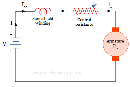
Since it is a series circuit, controlling the armature voltage is the same as the voltage supplied to the complete motor. The additional resistance will reduce the voltage given to the motor, which reduces the speed of the motor.
This method is more economical for constant torque drives. Such a method of controlling the speed is employed for motor driving cranes, hoists, trains, etc.
Shunted Armature control
A rheostat, that is, a variable resistance is connected in parallel with the motor armature winding. Hence called shunted armature control, also called as armature diverter control.
By reducing the resistance value of the diverter, the armature current can be reduced. If so, then flux per pole must increase(T α φIa) to maintain a constant torque.
This will cause an increase in current drawn from the supply and hence flux φ will increase and subsequently motor speed will decrease. Thus the speed can be controlled by varying the resistance in the diverter.
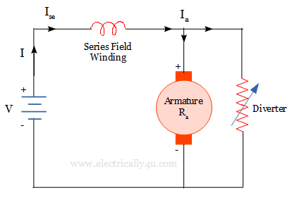
By using this method, the speed over a wide range can be obtained but below the normal speed. It is not economical due to considerable power losses in the diverter resistance. It is used in applications where slow speeds are essential at light loads.
Series – Parallel control Method
It is an efficient method of speed control of DC motor. When two or more similar series motors are employed in pairs, speed control can be achieved by combining the series resistance with motors in series and parallel connections.
The two machines are connected in series with each other and a starting resistance as shown below in figure(a). The starting resistance is gradually cut out as the motor attains the speed. Finally, the control resistance is removed completely. Now each motor has half of the line voltage across it. So the motor will run half of its normal speed.
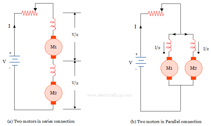
When the speed is to be increased, the two motors are connected in parallel with the starting resistance in series, as shown in figure(b). The starting resistance is gradually cut out when the motor picks up the speed.
Once the entire resistance is removed, the full line voltage is connected across the motors, hence the motor runs at a higher speed. But the current through each motor is half of the total current and so torque produced is lesser than series-connected motors. It offers great flexibility, reliable operation and power wastage is reduced.