Parallel Operation of DC Generators
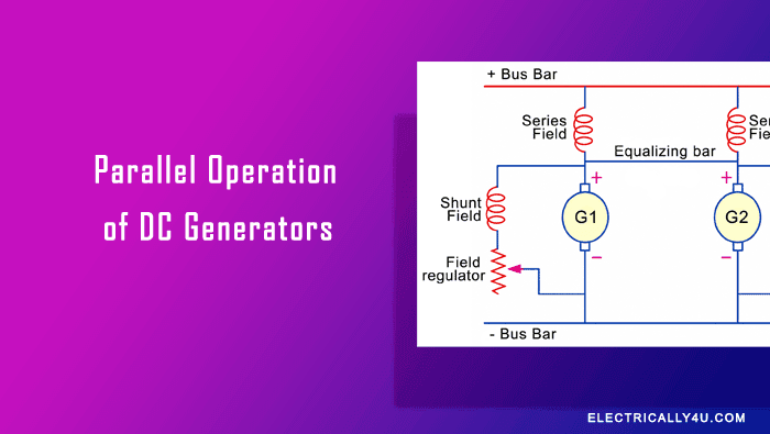
The parallel operation of DC generators is widely used in power stations because it provides a reliable, efficient, and flexible power supply. Instead of installing one large generator to meet the maximum load demand, power plants use several smaller DC generators connected in parallel. These generators can operate individually or together depending on the electrical load. This arrangement improves system reliability, makes maintenance easier, and allows future expansion without replacing the existing system.
Advantages of parallel operation of DC generators
The parallel operation of DC generators offers several important advantages over using a single large generator.
Continuous Power Supply : One of the biggest advantages is the continuity of service. If only one generator is installed and it fails due to a mechanical or electrical fault, the entire power station will stop supplying power. However, when multiple DC generators are connected in parallel, the remaining generators continue to supply electricity even if one generator is taken out of service. This makes the system more reliable, especially in industries, hospitals, and other places where uninterrupted power is essential.
Higher Operating Efficiency : Electrical demand changes throughout the day. During low load periods, running one small generator is more economical than operating a large generator at partial load. As the demand increases, another generator can be connected in parallel to share the additional load. Since generators operate most efficiently near their rated capacity, the parallel operation of DC generators helps reduce operating costs and improve overall efficiency.
Easy Maintenance and Repairs : Regular inspection and maintenance are necessary to ensure reliable generator performance. With parallel connected DC generators, one generator can be shut down for maintenance while the remaining generators continue supplying power. Likewise, if a generator develops a fault, it can be repaired without interrupting the electrical supply to consumers.
Easy Expansion of the Power Plant : As electricity demand grows, additional generators can be installed and connected in parallel with the existing units. This eliminates the need to replace the entire generating system and makes future expansion simple and economical.
Conditions for parallel operation
Let us consider Generator G₁ is already connected and supplying power to the load. Generator G₂ is ready to be connected. Protective devices such as fuses or circuit breakers are used to protect the generators from overloads and short circuits. Voltmeters and ammeters are also provided to monitor the terminal voltage and load current.
Before connecting Generator G₂ in parallel with Generator G₁, the following conditions must be satisfied.
1. Same polarity
The positive terminal of the incoming generator (G₂) must be connected to the positive bus-bar, and the negative terminal must be connected to the negative bus-bar.
If the polarity is reversed, the two generators will oppose each other. Since the internal resistance of a DC generator is very low, a very large current will flow immediately. This heavy current can damage the commutator, brushes, and generator windings and will usually cause the circuit breaker to trip or the fuse to blow.
2. Same terminal voltage
The terminal voltage of the incoming generator should be equal to the bus-bar voltage before it is connected.
- If the voltage of G₂ is lower than the bus-bar voltage, G₁ will supply power to both the load and G₂. As a result, G₂ will start running as a DC motor instead of a generator.
- If the voltage of G₂ is much higher than the voltage of G₁, the current in G₁ may reverse. In this case, G₁ will begin absorbing power and operate as a motor.
In practice, the incoming generator is usually adjusted to have a terminal voltage 1–2 V higher than the bus-bar voltage. After it is connected and starts supplying load, its voltage naturally drops because of armature reaction, armature voltage drops and slight reduction in field current.
A moving-coil paralleling voltmeter is commonly used to check both the voltage and polarity.
Procedure for parallel operation of DC generators
The following steps are used to connect an incoming DC generator to the existing power system.
- First, close the disconnect switch of the incoming generator to prepare it for connection.
- Start the prime mover and bring the generator to its rated operating speed.
- Adjust the field excitation so that the terminal voltage of the incoming generator becomes slightly higher than the bus-bar voltage.
- Once the voltage is properly adjusted, close the circuit breaker to connect the generator to the bus-bars.
Parallel operation of shunt DC generators
During the parallel operation of DC generators, the positive terminal of every generator is connected to the positive bus-bar, while the negative terminal is connected to the negative bus-bar. These bus-bars are heavy copper conductors that distribute electrical power throughout the station.
Suppose Generator G1 is already supplying power to the load. To connect Generator G2, its speed is first increased to the rated value. A voltmeter (V) is connected across the open switch S1, and the field current is adjusted until the voltmeter reads zero. At this point, the terminal voltage of the incoming generator is equal to the bus-bar voltage.
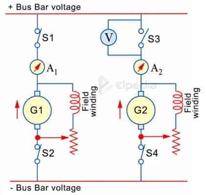
Now, the switch S4 is closed and after closing, Generator G2 becomes connected to the system but does not supply any current because both voltages are equal. This condition is known as the floating condition or a floating generator.
To make the incoming generator share the load, its induced EMF must be increased slightly above the bus-bar voltage by increasing the field excitation. The generator then begins to supply its share of the load current. If required, the field current of the running generator can be reduced slightly to maintain a constant bus-bar voltage.
Proper load sharing of DC generators is essential for stable operation. Shunt generators are well suited for parallel operation because their terminal voltage decreases slightly as the load increases. This natural voltage drop helps distribute the load automatically between the generators.
If one generator starts carrying more than its share of the load, its terminal voltage decreases slightly. This reduction limits any further increase in current, allowing the other generator to share more of the load. As a result, the generators remain stable and continue operating together without manual adjustment.
When a generator needs to be removed from service, its field current is gradually reduced until its ammeter reads zero. The circuit breaker is then opened, followed by the disconnect switch. This method avoids sudden disturbances to both the electrical system and the prime mover.
The following points should be remembered during the parallel operation of DC generators:
- Generators having the same no-load voltage share the load according to their voltage drops.
- Generators with different no-load voltages develop sufficient voltage drops so that their terminal voltages remain equal.
- A generator with lower voltage drop generally carries a larger portion of the load.
- Generators with different power ratings share the load in proportion to their rated capacities when they have similar voltage regulation.
Parallel operation of compound DC generators
The parallel operation of DC generators becomes more complicated when compound DC generators are used. If one generator starts supplying more current, its series field becomes stronger, increasing its generated EMF. This causes it to take an even greater share of the load, while the other generator loses load. Eventually, one generator may supply the entire load and drive the other generator as a motor, resulting in unstable operation.
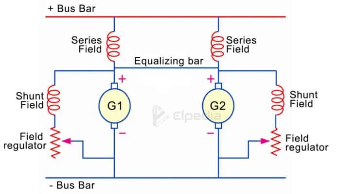
To prevent this problem, an equalizer bar is connected between the armature ends of the series field windings. The equalizer bar allows part of the increased current to flow through the other generator’s series field, balancing the excitation and ensuring proper load sharing. For satisfactory operation, all generators should have similar voltage regulation, and the series field resistance should be selected according to the generator ratings.
Parallel operation of series DC generators
The parallel operation of series DC generators is naturally unstable. If one generator develops a slightly higher EMF, it begins supplying more current. This strengthens its magnetic field further, while the other generator supplies less current and becomes weaker. Eventually, one generator supplies the entire load and may even drive the other generator as a motor.
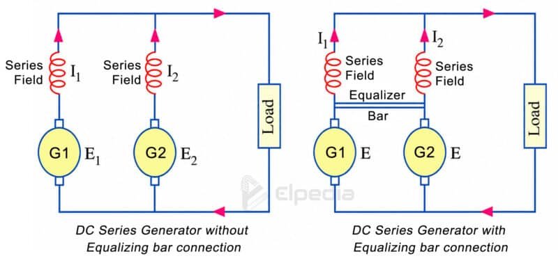
To avoid this instability, an equalizer bar is connected between the generators. It balances the current flowing through the series field windings and ensures that both generators share the load more equally.