Pitch Factor and Distribution Factor | Winding factor in Alternator
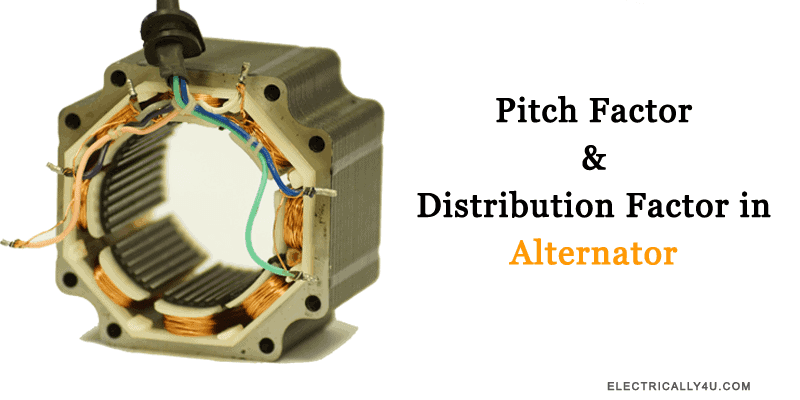
In an alternator, the generated EMF depends not only on the number of turns and the magnetic flux but also on the arrangement of the armature winding. Since practical alternator windings are generally short-pitched and distributed, the EMF generated by the individual coil sides does not add arithmetically. Instead, the induced EMFs combine as phasors, resulting in a reduction in the generated EMF.
Two important factors are used to account for this reduction: the pitch factor and the distribution factor. The pitch factor, also known as the coil span factor, accounts for the effect of short-pitching the coils, while the distribution factor accounts for the effect of distributing the winding across several slots under each pole.
The product of pitch factor Kp and distribution factor Kd is called as winding factor.
In this article, we will discuss the pitch factor and distribution factor, derive their expressions, and understand how they are used to determine the winding factor of an alternator.
Pitch factor
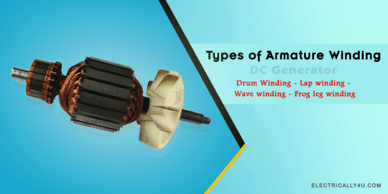
Before getting to know about the pitch factor and distribution factor in detail, you need to know about the armature winding in the alternator and its types.
Now, What is pitch factor?
The ratio of phasor sum of induced EMFs per coil to the arithmetic sum of induced EMFs per coil is known as pitch factor Kp or coil span factor Kc. Its value is always less than unity.
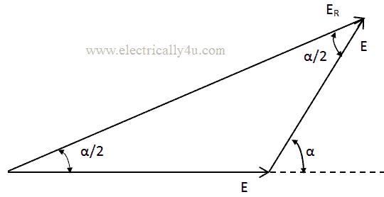
Let us consider, the coil has a pitch short by an angle α electrical degrees from the full pitch. The induced emf in each coil side be E. Now, if the coil is said to be full pitch, then total induced emf in the coil would be 2E.
For a coil, that is short-pitched by α electrical degrees, the resultant induced emf ER is the phasor sum of two voltages α electrical degrees.
![\[ E_R = 2E cos \frac{a}{2} \]](https://elpedia.com/wp-content/ql-cache/quicklatex.com-b052ed85718b3190947805da1f1b0c21_l3.png "Rendered by QuickLaTeX.com")
The formula for pitch factor is given by
![\[ \text{Pitch Factor, } K_p = \frac{\text{Phasor sum of coil side emfs}}{\text{Arithmetic sum of coil side emfs}} \]](https://elpedia.com/wp-content/ql-cache/quicklatex.com-91d6e2a7069d2bef6871089248e2dbc3_l3.png "Rendered by QuickLaTeX.com")
![\[ K_p = \frac{2Ecos\frac{a}{2}}{2E} = cos\frac{a}{2} \]](https://elpedia.com/wp-content/ql-cache/quicklatex.com-cd0fc6d2d1b5a78250b9c3f7f91d0769_l3.png "Rendered by QuickLaTeX.com")
The pitch factor in the above equation is for fundamental component of emf.
If the coil span is reduced by one slot, then the phase angle α between the induced EMFs in the two sides of the coil is given as
![\[ \alpha = \frac{180^\circ}{n} { \text{ where n is the number of slots per pole} \]](https://elpedia.com/wp-content/ql-cache/quicklatex.com-8edcd7fe26517588e88755c23b100e38_l3.png "Rendered by QuickLaTeX.com")
Distribution factor
If all the coil sides of any one phase under one pole are bunched in one slot, the winding obtained is known as concentrated winding.
The ratio of the phasor sum of the EMFs induced in all the coils distributed in a number of slots under one pole to the arithmetic sum of the EMFs induced(or to the resultant of EMFs induced in all coils concentrated in one slot under one pole) is known as breadth factor Kb or distribution factor Kd. Its value is always less than unity.
![\[K_d = \frac{\text{EMF induced in distributed winding}}{\text{EMF induced if the winding would have been concentrated}} \]](https://elpedia.com/wp-content/ql-cache/quicklatex.com-b4c01e93a337162e5701669e729c622c_l3.png "Rendered by QuickLaTeX.com")
![\[K_d = \frac{\text{Phasor sum of component emfs}}{\text{Arithmetic sum of component emfs}} \]](https://elpedia.com/wp-content/ql-cache/quicklatex.com-38dd33ecd8747cf0cf17d348e4e27636_l3.png "Rendered by QuickLaTeX.com")
Let n be the number of slots per pole.
m be the number of slots per pole per phase.
Ec be the induced emf in each coil side.
Angular displacement between the slots
![\[\beta = \frac{180^\circ}{n} \]](https://elpedia.com/wp-content/ql-cache/quicklatex.com-1cd01887337835e61f8e670a3f08bf7b_l3.png "Rendered by QuickLaTeX.com")
The EMFs induced in different coils of one phase under one pole are represented by side AC, CD, DE, EF,… which are equal in magnitude but differ in phase.[Say the magnitude be E and phase difference be 180 degrees]
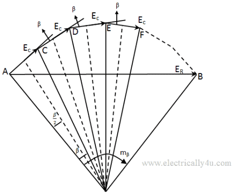
If bisectors are drawn on AC, CD, DE, EF, they would meet at a common point. This point would be the center of the circle having AC, CD, DE, EF as the chords. They represent the EMFs induced in the coils in different slots.
![\[\text{EMF induced in each coil side, E = AC }= 2 \times OA \times sin \frac{\beta}{2} \]](https://elpedia.com/wp-content/ql-cache/quicklatex.com-adc00af112d4350a9c35635787bed06e_l3.png "Rendered by QuickLaTeX.com")
![\[\text{Arithmetic sum of emf induced } = m\times 2\times OA \times sin \frac{\beta}{2} \]](https://elpedia.com/wp-content/ql-cache/quicklatex.com-206988c31ae9ec1966d592c1f3302cdd_l3.png "Rendered by QuickLaTeX.com")
The resultant emf can be obtained from the below equation,
![\[ E_R = AB = 2 \times OA \times sin \frac{AOB}{2} = 2 \times OA \times sin \frac{m\beta}{2} \]](https://elpedia.com/wp-content/ql-cache/quicklatex.com-949145a46d161e2ca46f290f5e9b512c_l3.png "Rendered by QuickLaTeX.com")
Thus the distribution factor can be obtained as
![\[K_d = \frac{\text{Phasor Sum of component emfs}}{\text{Arithmetic Sum of component emfs}} \]](https://elpedia.com/wp-content/ql-cache/quicklatex.com-950573b883e5e232ba2fb36e90b8ecd1_l3.png "Rendered by QuickLaTeX.com")
![\[K_d = \frac{2 \times OA \times sin \frac{m\beta}{2}}{m\times 2\times OA \times sin\frac{\beta}{2}} \]](https://elpedia.com/wp-content/ql-cache/quicklatex.com-c3b474be0f55b6484319b2dc36756366_l3.png "Rendered by QuickLaTeX.com")
![\[K_d = \frac{sin \frac{m\beta}{2}}{m \, sin \frac{\beta}{2}} \]](https://elpedia.com/wp-content/ql-cache/quicklatex.com-b783bc2a2389f76142c4c66105e767fe_l3.png "Rendered by QuickLaTeX.com")
So, from the obtained values calculated using the derived formulas of pitch factor and distribution factor, the winding factor is obtained by multiplying both, as shown below.
![\[K_w = K_p \, K_d \]](https://elpedia.com/wp-content/ql-cache/quicklatex.com-1c182455643e55b3b38151aaa922d1b6_l3.png "Rendered by QuickLaTeX.com")