Sumpner’s Test (Back to Back Test) of Transformer
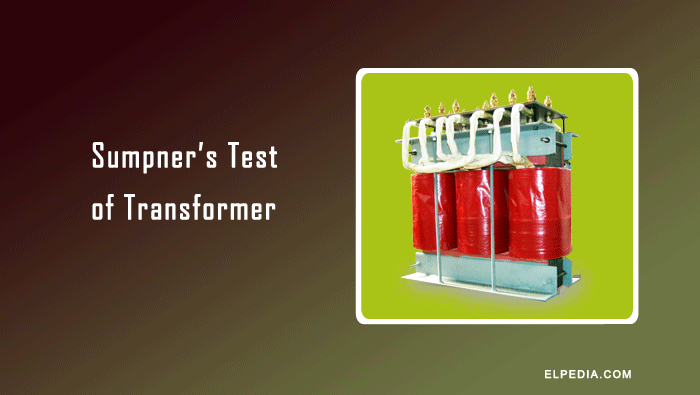
Sumpner’s test, also known as the back-to-back test, is an important method used to determine the losses and temperature rise of transformers under full-load conditions.
Unlike conventional load testing, this method requires very little power from the supply because the power consumed is mainly used to overcome the losses in the transformers.
It is particularly useful for testing large-capacity transformers, where providing a full-load arrangement is difficult and expensive.
In this article, we will discuss the working principle, circuit connections, procedure, and advantages of Sumpner’s test.
Why Sumpner’s test ?
Although the efficiency and voltage regulation of a transformer can be determined accurately using open-circuit and short-circuit tests, these tests do not directly determine the temperature rise under full-load operating conditions.
To measure the temperature rise, the transformer must operate at full load for several hours until it reaches a steady temperature.
Small transformers can be loaded using lamp banks or water loads. However, providing a suitable load for large-capacity transformers is difficult and results in considerable wastage of electrical energy.
Sumpner’s test is an economical method of testing two identical transformers under full-load conditions without connecting an actual external load.
The arrangement is similar in principle to the regenerative test used for DC machines.
In this test, the supply provides only the power required to compensate for the iron and copper losses of both transformers.
Therefore, full-load conditions can be maintained with relatively little power consumption.
Circuit Connections
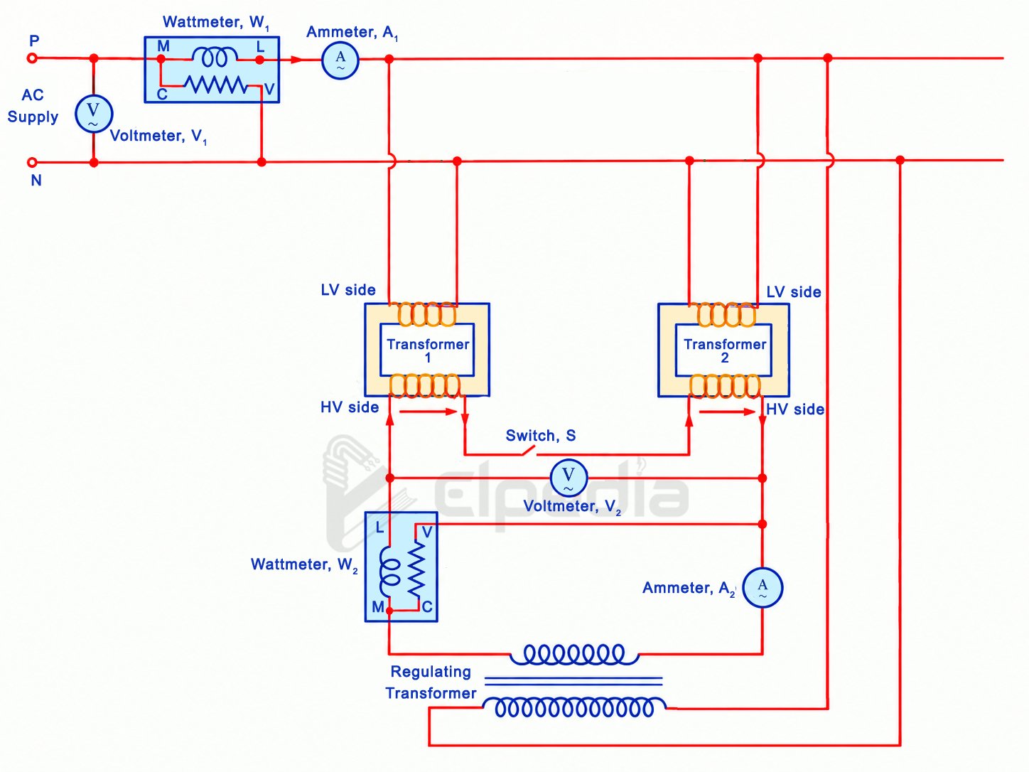
Two identical transformers are required to conduct Sumpner’s test. Their primary windings, usually the low-voltage windings, are connected in parallel across a single-phase AC supply.
A voltmeter (V1), an ammeter (A1), and a wattmeter (W1) are connected to measure the supply voltage, current, and input power, respectively. The supply voltage is adjusted to the rated voltage of the primary windings.
The secondary windings are connected in series opposition so that their induced EMFs cancel each other.
To verify the correct connection, one terminal of each secondary winding is connected together, and the voltage between the two remaining terminals is measured using a voltmeter (V2) with an appropriate range.
If the measured voltage is approximately twice the rated secondary voltage, the secondary windings are connected in series aiding.
In this case, the connections of either one secondary winding must be interchanged.
When the windings are correctly connected in series opposition, the measured voltage is approximately zero. The following figure shows the connection of Sumpner’s test of transformer.
Measurement of Iron Losses
When the secondary windings are connected in series opposition, their induced EMFs cancel each other, and ideally no current flows through the secondary circuit.
Consequently, the transformers operate under no-load conditions, and the primary currents are limited to their respective no-load currents.
The wattmeter (W1) measures the total input power supplied to both transformers. Since the secondary currents are zero, copper losses due to load current are negligible.
Therefore, the wattmeter reading represents approximately the combined iron losses of the two transformers.
Measurement of Full-Load Copper Losses
After measuring the iron losses, a low adjustable voltage is applied to the secondary circuit using a regulating transformer or autotransformer.
This voltage produces a circulating current through the secondary windings. The applied voltage is gradually adjusted until the ammeter (A2) indicates the rated secondary current.
Under this condition, both transformers carry their rated load currents even though no external load is connected.
The circulating current produces corresponding currents in the primary windings. Because the secondary windings are connected in series opposition, the load-related primary currents oppose each other at the supply connection and largely cancel, apart from differences in the transformers’ no-load currents.
The supply therefore provides mainly the power required to compensate for the iron and copper losses.
The wattmeter (W1) continues to measure the total input power, while the wattmeter (W2), connected in the regulating-voltage circuit, measures the power supplied to overcome the combined copper losses of both transformers.
Thus, the combined full-load copper losses are obtained from the reading of (W2), while the combined iron losses are obtained from the reading of (W1) before the circulating current is established.
Temperature-Rise Measurement
Once the rated secondary current has been established, the transformers are maintained under these test conditions for several hours.
Their winding and oil temperatures are monitored until the maximum steady-state temperature is reached.
The observed temperature rise helps assess the thermal performance of the transformers under full-load operation.
Although the transformers carry their rated secondary currents, their primary currents may not be exactly equal because their no-load currents differ in magnitude and phase.
Depending on the instantaneous phasor relationships, one transformer may draw a slightly higher primary current than the other. Consequently, their copper losses and temperature rises may differ slightly.
Sumpner’s test is particularly useful for large transformers because it enables full-load thermal testing without requiring a load capable of absorbing their entire rated output.
It also provides a practical means of determining the combined iron and full-load copper losses of the two transformers.
Advantages of Sumpner’s Test of Transformer
- Low power consumption: Only the power required to supply the iron and copper losses of both transformers is drawn from the source, making the test economical.
- Full-load testing: Both transformers can be tested under full-load conditions without connecting an actual external load.
- Temperature-rise measurement: The test allows transformers to operate under full-load conditions for several hours, enabling the measurement of winding and oil temperature rise.
- Loss determination: The combined iron losses and full-load copper losses of the two transformers can be determined.
- Efficiency calculation: The efficiency of the transformers can be calculated using the measured iron and copper losses at different load conditions.
- Suitable for large transformers: It is particularly useful for testing large-capacity transformers, for which arranging an actual full-load arrangement is difficult and costly.
- Reduced energy wastage: Compared with direct loading, the test avoids wasting most of the transformers’ rated output power in an external load.