Type Tests in Transformer
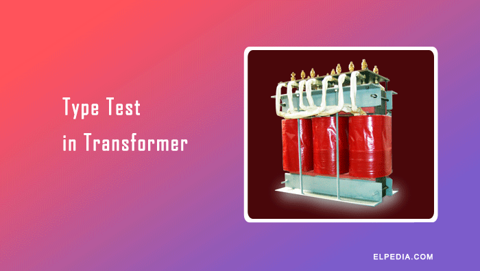
A type tests in transformer refers to a set of design verification tests carried out on one transformer of a given rating and construction, usually witnessed by the purchaser or a third-party inspector.
These tests confirm that the transformer design meets dielectric, thermal, mechanical, and functional requirements under conditions that simulate real-world operational stress.
A single passed type test qualifies all transformers built to the same design for series production.
Understanding the distinction between transformer testing types is essential:
- Routine tests are performed on every manufactured unit to catch manufacturing defects, includes winding resistance test, insulation resistance testing, ratio test, and open circuit test.
- Type tests are performed on a representative (prototype) unit to validate the design itself. It includes covering lightning impulse, temperature rise, and short circuit withstand.
- Special tests are carried out by agreement between buyer and manufacturer for non-standard requirements such as partial discharge test or dissolved gas analysis.
Type tests are essential for power transformers above approximately 1 MVA, as well as critical distribution transformers used in substations, wind farms, and industrial plants.
The main international standards for transformer testing include IEC 60076 (parts 1 through 5 and 11) and the IEEE C57 series (C57.12.00, C57.12.90, C57.12.91). This article aligns primarily with IEC 60076 terminology.
A successfully completed type test reduces technical and commercial risk over the 30–40 year expected lifetime of a transformer, providing the certification needed for connecting transformers to the public power grid.
Scope and Objectives of Type Testing
The aim of type testing is to verify dielectric strength, thermal performance, short circuit withstand capability, and functional characteristics of the transformer design.
Type tests ensure safety and reliability by confirming that engineering models match real-world behavior under extreme conditions.
Transformers commonly subjected to full type tests include:
- Large power transformers (e.g., 132/33 kV, 50 MVA units for transmission networks)
- Generator transformers and autotransformers
- Strategic distribution transformers (e.g., 33/11 kV, 16 MVA)
Key objectives of type testing:
- Confirm insulation coordination between windings and to ground
- Validate calculated temperature rise and copper losses
- Confirm safe behavior under through-faults (short circuit conditions)
- Confirm ratio and vector group under rated conditions
- Validate finite-element and thermal models used by design engineers
Power transformers handle voltages up to hundreds of kilovolts and are used for high-capacity power transmission, while distribution transformers operate at medium to low voltages like 11 kV and are designed for high load variations.
Type tests are crucial for transformers used in substations and power plants regardless of category.
Batch qualification saves time and cost by testing only prototypes rather than every unit-once a design passes, subsequent units rely on routine tests only.
Different Type Tests in Transformer
These tests form the backbone of transformer testing for design verification. Major type tests include:
- Insulation resistance test
- Dielectric type tests
- Temperature rise test
- Short circuit withstand test
- Transformation Ratio test
- Vector group test
- Magnetic balance test
- Magnetizing current test
- Winding resistance test
While some of these, like the ratio test or open circuit test also appear as routine tests, the type test version is often done at rated power and rated frequency, sometimes at elevated temperature, to stress the design.
Not every small distribution transformer receives the full high-energy tests due to cost and risk; instead, a representative unit for a whole family of ratings may be tested.
In practice, test sequences are agreed between manufacturer and purchaser, but must not fall below the minimum mandated in IEC/IEEE standards.
Dielectric Type Tests
Dielectric tests are performed to verify the ability of a transformer’s insulation system to withstand specified electrical stresses without insulation breakdown.
They assess the insulation between the high-voltage (HV) and low-voltage (LV) windings, between the windings and earth (including the core and other earthed parts), and between turns of the same winding, as applicable to each test.
These tests help ensure that the transformer can withstand the power-frequency voltages and transient overvoltages specified for its insulation system.
The applicable tests and test voltages depend on the transformer rating, insulation design, and relevant standards.
Key dielectric type tests include:
- Lightning impulse test (LI test): This test evaluates the transformer’s ability to withstand transient over-voltages caused by lightning. A standard lightning impulse waveform of 1.2/50 µs is generally used. The specified impulse voltage is applied to the designated terminals according to the applicable test procedure. Voltage and current oscillograms are examined for abnormal waveform changes that may indicate insulation failure.
- Switching impulse test: This test evaluates the insulation’s ability to withstand switching over-voltages. It is applicable to specified high-voltage transformer designs and voltage classes, particularly in extra-high-voltage systems.
- Applied AC withstand voltage test: It checks the insulation between a winding and earth, and between that winding and other windings connected to earth, as applicable. A specified power-frequency AC voltage is applied for the prescribed duration, commonly 60 seconds.
- Induced overvoltage test: In this test, an AC voltage is applied to one winding to induce an elevated voltage in the windings under test. It primarily evaluates turn-to-turn, layer-to-layer, and other winding insulation, as applicable. The test frequency is generally increased above the rated frequency to limit core flux and prevent magnetic saturation when applying the elevated voltage.
Insulation Resistance Test
The insulation resistance (IR) test is a preliminary assessment commonly performed before dielectric withstand tests. An insulation resistance tester, also known as a megohmmeter, applies a DC voltage and measures the resistance between HV–LV, HV–earth, and LV–earth.
A 5 kV DC test voltage may be used for certain power transformers, but the appropriate voltage depends on the transformer rating and the applicable test procedure.
The measurement duration must also follow the specified procedure; a one-minute reading is commonly used rather than assuming that 30 seconds is mandatory for all transformers.
Insulation resistance testing is generally treated as a preliminary or maintenance test rather than a dielectric type test under IEC 60076. The measured values should be recorded along with the test voltage, winding temperature, and other relevant conditions for future comparison.
Both power transformers and distribution transformers undergo applicable insulation assessments and dielectric tests, although the requirements and test levels vary according to their design and voltage ratings.
Temperature Rise Type Test
The temperature-rise test evaluates the thermal performance of a transformer under specified operating conditions. It verifies that the temperature rise of the transformer oil and windings remains within the permissible limits specified by the applicable standards.
The test also helps assess the effectiveness of the cooling system and the transformer’s ability to dissipate the heat generated by core and winding losses.
During the test, the transformer is is operated at rated test current until thermal equilibrium is reached. Oil and winding temperatures are monitored using top-oil thermometers, winding resistance method and fiber-optic sensors in modern power transformers.
The test duration depends on the transformer rating, cooling arrangement, and time required to reach thermal equilibrium. For large power transformers, the test may take many hours or longer.
Transformer losses are an important source of heat during operation. The following measurements provide the loss data required for thermal evaluation:
- Copper losses and stray losses are calculated from the short circuit test (load test), which measures the full-load losses in transformers. These losses contribute to winding and structural heating.
- Iron or core loss is calculated from the open circuit test, which measures no-load losses in transformers. This loss contributes to the heating of the transformer core and oil, even when the transformer supplies no load.
- Measured no load loss and load loss data become the reference for loss capitalization and tender evaluations.
The temperature-rise test is particularly important for large power transformers used in transmission and distribution networks. Excessive winding or oil temperatures can accelerate insulation ageing, reduce transformer service life, and affect operational reliability.
Short-Circuit Withstand Type Test
The short-circuit withstand test is an important special test used to verify the ability of a transformer to withstand the mechanical and thermal stresses produced by external short circuits.
During a fault, very high currents flow through the windings, generating intense electromagnetic forces that can cause winding deformation, displacement, or damage to the clamping structures and connecting leads.
During the test, the transformer is subjected to specified short-circuit current conditions. The test current and duration are determined according to the applicable standard and transformer specification.
The test requirements depend on the transformer design, rated characteristics, and specified short-circuit conditions.
A duration of 2 seconds is commonly used for assessing thermal withstand capability, unless otherwise specified or agreed. For very high short-circuit currents, a shorter duration may be applicable in accordance with the standard.
Before and after each circuit test, the following are checked:
The transformer is considered to have passed the test when the results demonstrate compliance with the applicable acceptance criteria.
These criteria include the absence of significant physical damage, acceptable changes in short-circuit impedance, and satisfactory results from the specified electrical measurements and inspections.
Any changes in winding resistance, transformation ratio, or other measured characteristics are evaluated against the relevant limits and pre-test measurements. No single impedance-change percentage should be treated as a universal acceptance limit for all transformers.
Transformation Ratio Test
The transformation ratio test verifies that the voltage ratio between the primary and secondary windings agrees with the specified value.
A suitable test voltage is applied to one winding, and the corresponding voltage in the other winding is measured. The measured ratio is compared with the calculated ratio at the specified tap positions to confirm accuracy.
The acceptable tolerance depends on the applicable standard and transformer specification.
This test helps verify the transformer’s intended voltage transformation ratio and identify incorrect winding connections or turns.
Vector Group Test
The vector group test verifies the winding connections, polarity, and phase displacement between the high-voltage (HV) and low-voltage (LV) windings of a three-phase transformer.
Vector groups such as Dyn11 and YNd1 indicate the winding connections and the phase displacement between the corresponding HV and LV voltage phasors.
The measured phase relationships are compared with the expected vector diagram to confirm the specified vector group.
Correct verification is essential when transformers are operated in parallel because incompatible voltage ratios, phase sequences, or phase displacements can cause circulating currents or other operational problems.
Magnetic Balance Test
The magnetic balance test is used to assess the magnetic circuit of a three-phase transformer. A low AC voltage is applied to one phase of a winding, while the voltages induced in the other phases are measured.
The procedure is repeated for the other phases, and the results are compared to assess the symmetry of the magnetic circuit.
The voltage distribution depends on the core construction and magnetic flux paths. Significant deviations from the expected pattern may indicate a magnetic circuit abnormality or a winding-related problem.
However, the magnetic balance test alone cannot conclusively identify inter-turn faults or determine the exact cause of an abnormal result; further diagnostic tests may be required.
Magnetizing Current Test
The magnetizing current test measures the current drawn by a transformer winding when rated voltage is applied at the specified frequency under no-load conditions, with the other winding open.
The measured current provides information about the magnetic behavior of the core and can help identify abnormalities associated with core construction, magnetic joints, or winding conditions.
For three-phase transformers, the no-load current in each phase may be compared to identify unusual differences.
The results depend on the core design, winding connections, applied voltage, and test conditions, so they should be evaluated against the manufacturer’s data or appropriate reference values.
Winding Resistance Test
The winding resistance test measures the DC resistance of each transformer winding. Measurements are taken at the specified tap positions, where applicable, and corrected for winding temperature when comparisons require a common reference temperature.
The results help identify poor electrical connections, damaged conductors, contact problems in tap changers, or other winding abnormalities.
For both single-phase and three-phase transformers, recording these test results during manufacture establishes reference values for future condition assessment.
Comparing field measurements with factory records can help identify changes in winding resistance, magnetic behavior, and other electrical characteristics during the transformer’s service life.