Losses in transformer
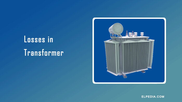
Losses in transformer occur during the transfer of electrical energy from the primary winding to the secondary winding through electromagnetic induction.
These losses convert part of the electrical energy into heat, reducing the efficiency of the transformer. Unlike an ideal transformer, which has no losses, a practical transformer cannot achieve 100% efficiency.
Losses in transformer are mainly classified into core losses (iron losses), copper losses, stray load losses, and dielectric losses.
Core losses consist of hysteresis loss and eddy current loss, while copper losses occur due to the resistance of the primary and secondary windings. Stray load losses result from leakage flux inducing eddy currents in conductors and structural components, whereas dielectric losses occur in the insulating materials.
Understanding these losses in transformer is essential for evaluating its efficiency, reducing energy wastage, and selecting suitable transformers for power transmission and distribution applications.
In this article, you will learn about the different losses in transformer and the practical ways to reduce the it.
How Losses in transformer affect the Efficiency
Transformer efficiency is the ratio of output power to input power, expressed as a percentage:
![\[\eta=\frac{\text{Output Power}}{\text{Input Power}}\times100%\]](https://elpedia.com/wp-content/ql-cache/quicklatex.com-abd2443802a881947cd19aca4c66d058_l3.png "Rendered by QuickLaTeX.com")
Transformer efficiency varies with load because core losses and copper losses behave differently. Core losses remain approximately constant at a constant supply voltage and frequency, whereas copper losses vary with the square of the winding current.
Maximum efficiency occurs when copper losses equal core losses. The corresponding load depends on the transformer’s design and loss characteristics rather than a fixed percentage of its rated capacity.
Transformer losses generate heat, increasing the temperatures of the windings, core, and other components. Excessive temperatures accelerate insulation ageing and can shorten the transformer’s service life.
As winding temperature rises, winding resistance also increases, resulting in higher copper losses at the same current. Therefore, effective cooling and thermal management are essential for reliable transformer operation.
Several operating conditions can increase transformer losses, including overloading, harmonic currents produced by power electronic equipment, inadequate cooling, and deterioration of insulating materials.
Overloading increases winding current and copper losses, while harmonic currents can increase additional winding and stray losses. Poor cooling raises operating temperatures, and moisture can compromise insulation performance.
These factors can reduce efficiency, increase maintenance requirements, and limit the transformer’s safe operating capacity.
For distribution transformers, all-day efficiency is particularly important because they may remain energized for 24 hours while operating at varying load levels. Since core losses continue even during periods of light loading, transformers with low core losses can offer better all-day efficiency.
In addition to losses, winding resistance and leakage reactance influence transformer voltage regulation, which determines how much the secondary terminal voltage changes between no-load and load conditions.
Types of Losses in Transformer
Losses in transformer are grouped into load-dependent types (copper loss, stray loss) and nearly constant types (core losses, some dielectric losses). Iron loss consists of hysteresis and eddy current losses. Standards typically evaluate core losses at rated voltage and frequency, and copper loss at rated current, to define efficiency points. The following sections detail each category with causes, dependencies, and mitigation methods.
Core Losses or Iron Losses
Core losses, also known as iron losses, are the power dissipated in a transformer’s magnetic core when it is subjected to alternating magnetic flux. They consist of two components: hysteresis loss and eddy current loss.
Core losses remain approximately constant when the supply voltage and frequency are constant, regardless of the load current.
They are commonly determined through an open-circuit (no-load) test, in which the secondary winding is left open and the primary winding is supplied at the specified voltage and frequency. Core losses become a significant part of total losses when a transformer operates at light load.
Hysteresis Loss
Hysteresis loss is the energy dissipated as heat in the transformer core during repeated cycles of magnetization and demagnetization.
As the alternating magnetic field changes direction, the magnetic domains within the core material continuously reorient. Because this magnetization process is not completely reversible, energy is dissipated during each cycle.
The energy dissipated per cycle per unit volume is represented by the area enclosed by the B–H hysteresis loop. The hysteresis loss can be approximated using the empirical Steinmetz equation:
![\[P_h=K_h\, f \,B_{\max}^{1.6}\,V\]](https://elpedia.com/wp-content/ql-cache/quicklatex.com-24b2e8ab98ac641cb80c68bb82b0b220_l3.png "Rendered by QuickLaTeX.com")
where Kh is the hysteresis coefficient, f is frequency, Bmax is maximum flux density, and V is volume of the magnetic core in cubic metres.
Hysteresis loss can be reduced by using core materials with narrow B–H hysteresis loops, such as cold-rolled grain-oriented (CRGO) silicon steel and amorphous metal alloys.
Proper core design and suitable operating flux density also help reduce this loss while maintaining the required voltage transformation.
Eddy Current Loss
Eddy current loss occurs when the alternating magnetic flux induces circulating currents within the electrically conductive core material, in accordance with Faraday’s law of electromagnetic induction.
These currents flow through the electrical resistance of the core material, producing heat and reducing transformer efficiency.
For a given core material and operating range, eddy current loss per unit volume is approximately proportional to the square of supply frequency, maximum magnetic flux density, and lamination thickness:
![\[P_e\propto f^2 \,B_{\max}^2\, t^2 \]](https://elpedia.com/wp-content/ql-cache/quicklatex.com-4e48ea5af636cabc090cae721d0657c7_l3.png "Rendered by QuickLaTeX.com")
where t is the thickness of an individual core lamination.
Eddy current losses in transformer are reduced by constructing its core from thin sheets of electrical steel, with each sheet electrically insulated from adjacent sheets. This laminated construction restricts the paths available for circulating currents and increases their effective resistance.
Electrical steel laminations commonly range from approximately 0.23 to 0.35 mm in thickness, although the actual thickness depends on the core material, design, and application.
Advanced core materials and construction techniques, including amorphous metal alloys, grain-oriented electrical steel, and optimized core joints, can further reduce core losses. The effectiveness of each method depends on the material properties, operating conditions, and transformer design.
Copper Losses in Transformer
Copper losses are the power dissipated as heat due to the electrical resistance of the primary and secondary windings. They are also known as winding losses, ohmic losses, or resistive losses. Although copper is commonly used as the winding conductor, some transformers use aluminium windings.
Copper losses depend on the winding current and resistance and are expressed as:
![\[ P_{\text{cu}}=I_p^2R_p+I_s^2R_s \]](https://elpedia.com/wp-content/ql-cache/quicklatex.com-7142b4f751d8a687fd2523de5b1a0f39_l3.png "Rendered by QuickLaTeX.com")
where Ip and Is are the primary and secondary winding currents, respectively, and Rp and Rs are their corresponding resistances.
At a constant winding resistance, copper losses vary approximately with the square of the load current. Therefore, if the load current doubles, the copper losses increase by approximately four times.
As the load increases, copper losses become a larger part of the total transformer losses and can significantly affect efficiency, winding temperature, and insulation life.
Copper losses in transformer can be reduced through appropriate transformer design and maintenance practices:
- Thicker conductors have lower electrical resistance for the same material and length.
- Minimize unnecessary conductor length while maintaining the required number of turns, insulation clearances, and electrical performance.
- Properly designed, tightened, and maintained joints help prevent excessive contact resistance and localized heating.
- Copper or appropriately designed aluminium windings can provide the required electrical performance at an acceptable cost and size.
- Proper cooling limits winding temperature and thermal stress. Lower winding temperatures also reduce conductor resistance and, consequently, copper losses at a given current.
Stray Losses and Dielectric Losses
Although stray load losses and dielectric losses are generally smaller than core and winding losses, they contribute to transformer heating, insulation ageing, and overall reliability.
Stray losses are additional losses caused primarily by leakage magnetic flux inducing eddy currents in transformer windings and conducting structural components.
These losses in transformer can occur in tank walls, clamping plates, bolts, and other metallic parts exposed to leakage flux. Stray load losses generally increase with load current and may become more significant at higher loads.
Stray losses can be reduced through careful core and winding design to control leakage flux, appropriate placement of structural components, and the use of magnetic shields or suitably selected non-magnetic materials where appropriate. These measures help minimize unwanted eddy currents and localized heating.
Dielectric losses are the electrical energy dissipated as heat in insulating materials subjected to an alternating electric field. In transformers, these losses occur in materials such as insulating oil, paper, pressboard, and other solid insulation.
Their magnitude depends on factors including the insulation material, operating voltage and frequency, temperature, moisture content, and contamination.
Moisture ingress, insulation deterioration, and contamination can increase dielectric losses and weaken the insulation system. Regular transformer oil testing helps assess its insulating condition and detect potential problems.
Tests such as dielectric dissipation factor (tan delta), moisture content, and dielectric breakdown voltage provide complementary information about insulation quality.
Appropriate maintenance and timely corrective action help improve transformer reliability and extend insulation life.
Practical Ways to Reduce Transformer Losses
Reducing core losses and copper losses improves the overall efficiency of the transformer, lowers operating costs, and supports climate goals. Here is a summary of actionable measures:
Loss Type | Reduction Strategy |
|---|---|
Core losses | Use CRGO or amorphous cores; thin laminations; design for optimal flux density |
Copper losses | Adequately sized conductors; compact windings; efficient cooling |
Stray losses | Control leakage flux paths; non-magnetic structural parts |
Dielectric losses | High-purity insulating oil; moisture control; periodic DGA and tan-delta testing |
Using cold-rolled grain-oriented (CRGO) silicon steel in transformer cores helps reduce hysteresis and eddy current losses. Preventive maintenance is also essential for detecting developing faults, maintaining insulation quality, and minimizing avoidable energy losses.
For new installations, selecting high-efficiency transformers that comply with applicable energy-efficiency standards can reduce operating losses and lifetime energy consumption compared with older, less efficient units.
The actual savings depend on transformer rating, loading profile, core and winding losses, operating conditions, and service life.