Electrical Resistance and Conductance: Definitions, Formulas, and Practical Applications
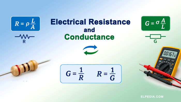
Electrical resistance and conductance are two sides of the same coin. One describes how a component opposes current flow; the other describes how freely it allows current to pass.
Together, they govern the behavior of every electrical and electronic circuit, from a simple light bulb to a high-voltage transmission line.
This guide covers their definitions, formulas, units, temperature behavior, measurement methods, and practical applications, with worked numerical problems to reinforce each concept.
Key Takeaways
- Electrical resistance is the opposition to current flow, measured in ohms (Ω), while conductance measures how easily current flows, measured in siemens (S). They are exact reciprocals: R = 1/G and G = 1/R.
- Ohm’s law (V = I·R) links voltage, current, and resistance. A 230 V heater drawing 4 A, for example, has a resistance of 57.5 Ω. Electrical engineers use this relationship daily for measuring resistance and sizing components.
- Resistance depends on material (resistivity), length, cross-sectional area, and temperature. The formula R = ρ·L/A captures the geometry and material dependence; copper’s resistivity is about 1.68×10⁻⁸ Ω·m at 20 °C.
- Conductance (G = I/V) and the geometry-based formula G = A/(ρ·L) guide the design of low resistance paths (busbars, power cables) and high resistance elements (heating elements, resistors) across practical applications.
- Elpedia connects theory to practice below with worked numerical problems, side-by-side comparisons (resistance vs resistivity, conductance vs conductivity), and real-world use cases in power, electronics, and electrical measurements.
What Is Electrical Resistance?
Electrical resistance is the opposition a material offers to the flow of electric current.
When electric current passes through a conducting material, moving electrons collide with atoms and lattice vibrations. These collisions convert electrical energy into heat, a process called Joule heating.
The physical mechanisms behind resistance are the same whether the conductor is a copper wire carrying power or a nichrome coil in an electric stove.
Resistance is a macroscopic property of a given object. It depends not only on the material but also on the component’s shape, length, and cross-sectional area.
A copper busbar and a copper wire made from the same alloy have different resistances because their geometries differ.
Voltage acts as the “electrical pressure” that pushes electric charge through a circuit. Current is the resulting flow of charge.
Resistance is the friction in that flow; higher resistance results in less current flowing through a circuit for a given voltage.
Components whose voltage and current share a linear relationship are called ohmic. Metallic wires and fixed resistors within moderate temperature ranges fall into this category and obey Ohm’s law.
Non-ohmic components, such as diodes, thermistors, and incandescent lamp filaments, exhibit curved V-I characteristics; their resistance changes with applied voltage or temperature.
Ohm’s Law and Basic Resistance Formula
Ohm’s law defines the relationship between resistance, voltage, and current as R = V / I. The same relationship can be rearranged into two other useful forms: V = I·R and I = V/R.
These three forms let engineers determine any one quantity when the other two are known.
Example 1: Finding Current
A 12 V battery is connected to a 3 Ω resistor. The current through the resistor is:
![\[I = \frac{V}{R} = \frac{12}{3} = 4\text{ A} \]](https://elpedia.com/wp-content/ql-cache/quicklatex.com-af7755332f2ef6df96c46bfd301b7f62_l3.png "Rendered by QuickLaTeX.com")
Example 2: Finding Resistance
A 230 V electric kettle draws a current of 10 A. Its resistance is:
![\[R = \frac{V}{I} = \frac{230}{10} = 23\ \Omega \]](https://elpedia.com/wp-content/ql-cache/quicklatex.com-effab38dfba71aaff759b2bcfcae3774_l3.png "Rendered by QuickLaTeX.com")
Therefore, the resistance of the kettle is 23 Ω. This relatively low resistance allows a large current to flow, producing the electrical power required for rapid heating.
For a uniform conductor, resistance also follows a geometry-based formula:
![\[R = \rho . \frac{L}{A} \]](https://elpedia.com/wp-content/ql-cache/quicklatex.com-b186f19c830ba0af27624f38f0d62a4e_l3.png "Rendered by QuickLaTeX.com")
Here ρ (rho) is the material’s resistivity in Ωm, L is the length in meters, and A is the cross-sectional area in m².
Resistance increases with the length of the conductor and is inversely proportional to the cross-sectional area.
Doubling the length of the conductor doubles its resistance and Doubling the cross-sectional area reduces its resistance by half.
This is why power cables are thick and short runs are preferred for low losses. Thicker wires have lower resistance because they offer a wider path for electrons.
Electrical engineers routinely combine Ohm’s law with R = ρL/A to size conductors for specific current levels and acceptable voltage drop limits (often below 3-5% in building wiring).
Unit of Resistance and the Concept of the Ohm
Resistance is measured in ohms (Ω), named after Georg Simon Ohm, who formulated the law relating voltage and current in 1827.
One ohm is defined as the resistance between two points when a potential difference of 1 V produces a current of 1 A.
Unit | Symbol | Magnitude |
|---|---|---|
Milliohm | mΩ | 10⁻³ Ω |
Ohm | Ω | 1 Ω |
Kiloohm | kΩ | 10³ Ω |
Megaohm | MΩ | 10⁶ Ω |
Fixed resistor values are printed directly (e.g., “4.7 kΩ”) or encoded with color bands. Use our resistor color code calculator to find the resistor values from the color bands.
Equipment nameplates often list rated voltage and current, from which resistance R can be derived using Ohm’s law.
Factors Affecting Resistance
Electrical resistance is not a fixed number stamped permanently on a component. It shifts with material type, geometry, temperature, frequency, and even mechanical strain.
Temperature Coefficient of Resistance
The temperature coefficient of resistance, denoted α, quantifies how much a material’s resistance R changes per degree Celsius relative to a reference temperature T₀ (usually 20 °C).
The approximate linear formula for metals within a moderate range is:
![\[R(T) = R_0[1+\alpha (T-T_0)] \]](https://elpedia.com/wp-content/ql-cache/quicklatex.com-c7de62503bf9a4f194d2ac30319c65bf_l3.png "Rendered by QuickLaTeX.com")
R₀ is resistance at T₀, α is the temperature coefficient in /°C, and T is the operating temperature. Typical α values at 20 °C: copper ≈ 0.00393/°C, aluminium ≈ 0.0043/°C, tungsten ≈ 0.0045/°C, and nichrome ≈ 0.00017/°C.
Numerical example: A copper element with R₀ = 50 Ω at 20 °C and α = 0.004/°C. Find its resistance at 80 °C.
Using the formula of temperature coefficient of resistance,
![\[R(T)=R_0[1+\alpha(T-T_0)] \]](https://elpedia.com/wp-content/ql-cache/quicklatex.com-d62fff00519522d7f48ca8ed00bc34a7_l3.png "Rendered by QuickLaTeX.com")
![\[R(80)=50[1+0.004(80-20)] \]](https://elpedia.com/wp-content/ql-cache/quicklatex.com-05461ab0d61259d07840a4925b23d9f1_l3.png "Rendered by QuickLaTeX.com")
![\[R(80)=50\times1.24=62\ \Omega \]](https://elpedia.com/wp-content/ql-cache/quicklatex.com-cdcec53e5196c1f9abd50881ec7c53b2_l3.png "Rendered by QuickLaTeX.com")
Therefore, the resistance increases from 50 Ω to 62 Ω when the temperature rises from 20 °C to 80 °C.
The effect of temperature is different for metals and semiconductors. Metals generally have a positive temperature coefficient, meaning their resistance increases as temperature rises.
Semiconductors and NTC thermistors generally have a negative temperature coefficient, so their resistance decreases as temperature increases.
PTC thermistors have a positive temperature coefficient and their resistance increases significantly with temperature. This property makes them useful for temperature sensing, overcurrent protection, and other applications.
The temperature dependence of resistance is also used in resistance thermometers, which measure temperature by detecting the change in electrical resistance of a sensing element.
Practical Example: Incandescent Lamp
The resistance of an incandescent lamp filament changes considerably with temperature. When the lamp is switched on, the filament is initially cold and has a much lower resistance than it has during normal operation. As the filament heats up, its resistance increases significantly.
Consequently, the lamp draws a high inrush current immediately after switching on. As the filament reaches its normal operating temperature, its resistance increases and the current falls to its normal operating value.
This illustrates an important practical point: the resistance of a component can change significantly during operation as its temperature changes.
What Is Conductance?
Conductance is a measure of how easily a component or material allows electric current to flow. It is the reciprocal of resistance.
Therefore, a component with low resistance has high conductance, while a component with high resistance has low conductance. It is is represented by the symbol (G) and is given by,
![\[G = \frac{1}{R} \text{ and } R = \frac{1}{G} \]](https://elpedia.com/wp-content/ql-cache/quicklatex.com-227e7019bb1d031570dd0197bf4c3b85_l3.png "Rendered by QuickLaTeX.com")
Using the Ohm’s law (R = V/I), the formula for conductance is
![\[G = \frac{I}{V} \]](https://elpedia.com/wp-content/ql-cache/quicklatex.com-da273f773893ccc58739c6e53c300b70_l3.png "Rendered by QuickLaTeX.com")
Conductance is measured in siemens (S), a unit equivalent to A/V. The older name “mho” (ohm spelled backward, symbol ℧) still appears in some legacy texts.
High conductance corresponds to low resistance; low conductance corresponds to high resistance. For example, a 0.5 Ω busbar has G = 1/R = 1/0.5 = 2 S, while a 10 kΩ resistor has G = 1/10,000 = 0.0001 S (0.1 mS).
Conductance is particularly useful when analyzing parallel circuits. In a parallel network, the total conductance is simply the sum of the individual conductances:
![\[G_{\text{total}}=G_1+G_2+G_3+\cdots \]](https://elpedia.com/wp-content/ql-cache/quicklatex.com-d953b0a37d554df71523b92c140a6c23_l3.png "Rendered by QuickLaTeX.com")
This makes parallel-circuit calculations convenient because there is no need to repeatedly use the reciprocal formula for resistance.
For a deeper look at combining resistors, see the article on series and parallel combination of resistors.
Conductance Formula, Unit, and Relationship to Geometry
Conductance can be calculated from the current and voltage using,
![\[\boxed{G = \frac{I}{V}} \]](https://elpedia.com/wp-content/ql-cache/quicklatex.com-2387ff670812f1517481786172aebdb3_l3.png "Rendered by QuickLaTeX.com")
For a linear or ohmic component, Ohm’s law gives (V=IR). Therefore,
![\[\boxed{G=\frac{1}{R}}\]](https://elpedia.com/wp-content/ql-cache/quicklatex.com-5ddbd3e0552c75087792ae2f6fcbf1c9_l3.png "Rendered by QuickLaTeX.com")
The conductance of a uniform conductor can also be determined from its physical dimensions:
![\[\boxed{G = \frac{A}{\rho. L}} \]](https://elpedia.com/wp-content/ql-cache/quicklatex.com-191c75c3b01d063cf34ac0dd08e48117_l3.png "Rendered by QuickLaTeX.com")
This equation is the reciprocal of the resistance formula.
Since electrical conductivity (σ) is the reciprocal of resistivity,
![\[\sigma=\frac{1}{\rho}\]](https://elpedia.com/wp-content/ql-cache/quicklatex.com-3ac507bf029fc57a999c0eb64a43478b_l3.png "Rendered by QuickLaTeX.com")
The conductance can also be written as,
![\[\boxed{G=\frac{\sigma A}{L}}\]](https://elpedia.com/wp-content/ql-cache/quicklatex.com-87eff02a0bf7158c99964c31d0822009_l3.png "Rendered by QuickLaTeX.com")
This shows that conductance depends on the material, cross-sectional area, and length of the conductor.
Conductance is directly proportional to cross-sectional area and inversely proportional to length.
The unit of conductance, the siemens (S), spans a wide range in practice: microsiemens (µS) for leakage and water-quality sensors, millisiemens (mS) for sensor circuits, and full siemens for large conductors.
For example, microsiemens may be used when measuring very small conductances, such as leakage or the electrical conductivity of water, while millisiemens are common in sensor and electronic circuits. Large conductors can have conductances measured in siemens.
Worked example: Consider a 2 m long copper wire with a cross-sectional area of 10 mm². At 20 °C, the electrical conductivity of copper is approximately 5.95×10⁷ S/m.
Using the formula of conductance,
![\[ G=\frac{\sigma A}{L}\]](https://elpedia.com/wp-content/ql-cache/quicklatex.com-953ea7e507517af693408f1d36cbf160_l3.png "Rendered by QuickLaTeX.com")
![\[G=\frac{(5.95\times10^7)(10\times10^{-6})}{2} \]](https://elpedia.com/wp-content/ql-cache/quicklatex.com-da6fb1f6198d185c2ad3c591ec94f78d_l3.png "Rendered by QuickLaTeX.com")
![\[G = 297.5\text{ S} \]](https://elpedia.com/wp-content/ql-cache/quicklatex.com-12f1bd4304e3e5f592dfc41f040ebbe3_l3.png "Rendered by QuickLaTeX.com")
The corresponding resistance is calculated as,
![\[ R=\frac{1}{G}\]](https://elpedia.com/wp-content/ql-cache/quicklatex.com-458dc9308ca34862520c75f8f5eae421_l3.png "Rendered by QuickLaTeX.com")
![\[R=\frac{1}{297.5} = 0.00336\, \Omega \]](https://elpedia.com/wp-content/ql-cache/quicklatex.com-d1cd899eaed609443c72e16cf1fbf26c_l3.png "Rendered by QuickLaTeX.com")
Thus, the wire has very high conductance and very low resistance, which is expected for a short, thick copper conductor.
Relationship Between Resistance, Conductance, Resistivity, and Conductivity
Resistance (R) and conductance (G) describe the electrical behavior of a particular component or conductor with a specific size and shape.
In contrast, resistivity (ρ) and conductivity (σ) are intrinsic properties of a material. They describe how the material itself opposes or allows the flow of electric current, independent of the conductor’s size and shape.
Resistivity (ρ, in Ωm) is the intrinsic measure of how a material opposes conduction. The resistivity of materials varies: copper ≈ 1.68×10⁻⁸ Ω·m, aluminium ≈ 2.65×10⁻⁸, nichrome ≈ 100×10⁻⁸, silicon ≈ 640 Ω·m, and Teflon > 10¹³ Ω·m.
Conductivity (σ = 1/ρ, in S/m) describes a material’s ability to conduct electric current per unit field per unit dimension. Copper’s conductivity is about 5.96×10⁷ S/m; deionized water is near 5.5×10⁻⁶ S/m.
Quantity | Symbol | Unit | Describes | Geometry-dependent? |
|---|---|---|---|---|
Resistance | R | Ω | A specific component | Yes |
Resistivity | ρ | Ω·m | Bulk material | No |
Conductance | G | S | A specific component | Yes |
Conductivity | σ | S/m | Bulk material | No |
Key formulas tying them: R = ρL/A, G = A/(ρL), G = σA/L, R = 1/G, σ = 1/ρ.
Resistance and Conductance in DC and AC Circuits
In DC circuits, resistance (R) and conductance (G) describe the relationship between voltage and current for ohmic components. Resistance determines how strongly a component opposes current flow, while conductance indicates how easily current flows through it.
The power dissipated by a resistive component can be calculated using any of the following equivalent expressions,
![\[ P=VI=I^2R=\frac{V^2}{R} \]](https://elpedia.com/wp-content/ql-cache/quicklatex.com-5b1ece7d56679a085653ccec83ab296a_l3.png "Rendered by QuickLaTeX.com")
Resistance ratios are also used in circuit-analysis techniques such as the current divider rule, which determines how current is distributed among parallel branches.
In AC circuits, resistance alone is not sufficient to describe the behavior of components such as inductors and capacitors because these components introduce phase differences between voltage and current.
The concept of resistance is therefore extended to impedance, represented by Z = R + jX, where R is the resistance and X is reactance contributed by reactive elements such as inductors and capacitors (capacitance and inductance).
The reciprocal of impedance is admittance, represented by Y = G + jB, where G is the conductance and B is the susceptance.
These complex quantities allow engineers to analyze both the magnitude and phase relationship between voltage and current in AC circuits.
For more on how real and reactive power interact, see the article on real power, reactive power, and apparent power.
The resistance of a conductor can also change when the frequency of an AC current increases. At higher frequencies, two important effects become significant: skin effect and proximity effect.
These effects reduce the effective cross section available to current at higher frequencies, raising effective resistance. This is why RF engineers use thin, flat conductors or Litz wire.
Resistance and conductance form the foundation for understanding electrical circuits. Their concepts are extended to impedance and admittance for AC circuit analysis.
Electrical engineers use impedance and admittance in applications such as AC power-system analysis, filter design, RF circuits, and antenna matching. Although these applications involve more advanced concepts, they are fundamentally based on the basic principles of resistance and conductance.
Difference Between Resistance and Conductance (and Related Concepts)
Resistance and conductance are reciprocals that describe the same physical reality from opposite perspectives. The tables below lay out the contrasts.
Resistance vs Conductance
Aspect | Resistance (R) | Conductance (G) |
|---|---|---|
Definition | Opposition to current flow | Ease of current flow |
Formula | R = V/I | G = I/V |
Unit | Ohm (Ω) | Siemens (S) |
Series circuits | Resistances add directly | Conductances combine reciprocally |
Parallel circuits | Resistances combine reciprocally | Conductances add directly |
High value means | Less current passing for a given voltage | More current passing for a given voltage |
Resistance vs Resistivity
Aspect | Resistance (R) | Resistivity (ρ) |
|---|---|---|
Describes | A specific component or element | A bulk material property |
Unit | Ω | Ω·m |
Depends on geometry? | Yes (length, area) | No |
Example | 23 Ω kettle element | Copper: 1.68×10⁻⁸ Ω·m |
Conductance vs Conductivity
Aspect | Conductance (G) | Conductivity (σ) |
|---|---|---|
Describes | A specific path between two points | Bulk material property |
Unit | S | S/m |
Depends on geometry? | Yes | No |
Example | 298 S for a 2 m, 10 mm² copper wire | Copper: 5.96×10⁷ S/m |
Measuring Resistance and Conductance in Practice
In practical electrical measurements, resistance is usually measured directly using an ohmmeter or digital multimeter (DMM). Conductance can then be calculated from the measured resistance using G = 1/R.
Resistance measurements are useful for identifying circuit problems such as open connections, damaged components, poor connections, and degraded insulation.
To measure the resistance of a component using a multimeter, first de-energize the circuit and isolate the component from the rest of the circuit. Connect the meter probes across the component and read the resistance shown on the display.
Depending on the application, resistance measurements may range from milliohms to megaohms.
For an operating circuit where power cannot be switched off, resistance can be determined indirectly by measuring the voltage across the device and the current flowing through it using the formula, R = V / I.
For example, if a heater operates at 240 V and draws 4 A, then its resistance can be determined as, R = 240 / 4 = 60 Ω. It represents the heater’s resistance under its operating condition.
For very low resistance, such as that of busbars, cable joints, and transformer windings, ordinary two-wire measurements can be affected significantly by the resistance of the test leads and connections. A four-wire (Kelvin) measurement is therefore used to obtain a more accurate result.
For very high resistance, such as cable insulation and equipment insulation, an insulation resistance tester (megohmmeter or megger) is used.
These instruments apply a DC test voltage, commonly 500 V to 1000 V for many applications, and measure the resulting insulation resistance, typically in megaohms (MΩ) or gigaohms (GΩ).
You can use our series and parallel resistance calculator for quick network computations.
Some LCR meters and impedance analyzers can measure and display resistance and conductance along with other electrical parameters at a specified AC test frequency.
This makes them useful for analyzing components and circuits under AC conditions.
Solved Numerical Problems on Resistance and Conductance
Problem 1: Basic Ohm’s Law
Given: V = 120 V, I = 2 A.
Resistance can be determined from the equation,
![\[R = \frac{V}{I} = \frac{120}{2} = 60 \, \Omega \]](https://elpedia.com/wp-content/ql-cache/quicklatex.com-c135ce601c180eac66a401dcb6a329fa_l3.png "Rendered by QuickLaTeX.com")
Its conductance is determined as,
![\[G = \frac{1}{R} = \frac{1}{60} = 0.0167\, S \]](https://elpedia.com/wp-content/ql-cache/quicklatex.com-f7b6668998214495f06560ab8b91153c_l3.png "Rendered by QuickLaTeX.com")
Problem 2: Geometry-Based Resistance and Conductance
Given: A 100 m copper cable has a cross-sectional area = 10 mm² = 10×10⁻⁶ m², ρ = 1.68×10⁻⁸ Ω·m.
Resistance can be determined from the equation,
![\[R = \frac{\rho L}{A} \]](https://elpedia.com/wp-content/ql-cache/quicklatex.com-8c3750e9836c1bdc8f5c0ec24b0bcd08_l3.png "Rendered by QuickLaTeX.com")
![\[R = \frac{(1.68\times10^{-8} \times 100)}{(10\times10^{-6})} = 0.168\, \Omega \]](https://elpedia.com/wp-content/ql-cache/quicklatex.com-7e29d946e93d9758da3b0e1379ba2387_l3.png "Rendered by QuickLaTeX.com")
![\[G = \frac{1}{R} = 1/0.168 = 5.95\, S \]](https://elpedia.com/wp-content/ql-cache/quicklatex.com-30b0d42fdb68ceb97cf495e7340e5c81_l3.png "Rendered by QuickLaTeX.com")
This 0.168 Ω is low resistance, suitable for power distribution. But over a long run at high current (say 100 A), the voltage drop is V = IR = 100 × 0.168 = 16.8 V, which may exceed limits in a 230 V system.
Problem 3: Temperature Coefficient
Given: R0 = 50 Ω at T0 = 20 °C, α = 0.004/°C. Find R at 80 °C.
Using the temperature coefficient of resistance formula,
![\[R(80) = 50\times [1+0.004\times (80-20)] \]](https://elpedia.com/wp-content/ql-cache/quicklatex.com-acd528351da699c881a3a353ac3211d0_l3.png "Rendered by QuickLaTeX.com")
![\[R(80) = 50 \times 1.24 = 62 \,\Omega \]](https://elpedia.com/wp-content/ql-cache/quicklatex.com-9a9eb8b897f8311ca82c3a5c4061fd53_l3.png "Rendered by QuickLaTeX.com")
The resistance rose by 24%, which engineers must account for when sizing conductors for hot environments.
Problem 4: Series/Parallel Network
Given: R₁ = 10 Ω and R₂ = 15 Ω in series; this combination is in parallel with R₃ = 50 Ω.
R1 and R2 and connected in series,
![\[R_{\text{series}} = R_1 + R_2 = 10 + 15 = 25\, \Omega \]](https://elpedia.com/wp-content/ql-cache/quicklatex.com-6f242a874c5e2498ff4110fe5f68905a_l3.png "Rendered by QuickLaTeX.com")
It is connected in parallel with R3, thus the total resistance is,
![\[\frac{1}{R_{\text{total}}} = \frac{1}{25} + \frac{1}{50} = \frac{3}{50}\]](https://elpedia.com/wp-content/ql-cache/quicklatex.com-fce87142c3cbc69970c81ba35bb09966_l3.png "Rendered by QuickLaTeX.com")
![\[R_{\text{total}} = \frac{50}{3} = 16.67 \,\Omega \]](https://elpedia.com/wp-content/ql-cache/quicklatex.com-cadef2ded3e3895f6d767435d4d0006d_l3.png "Rendered by QuickLaTeX.com")
![\[G_{\text{total}} = \frac{1}{16.67} = 0.06\, S \]](https://elpedia.com/wp-content/ql-cache/quicklatex.com-f4c1985ca451027817fc1ffb391efc2a_l3.png "Rendered by QuickLaTeX.com")
For more on combining resistors, our source transformation guide covers equivalent circuit techniques.
Applications of Resistance and Conductance
Resistance and conductance shape the design of every electrical system, from household appliances to industrial power grids.
High resistance applications: Resistors are components added to circuits to control current and voltage. Voltage dividers, sensor bridges, and current-limiting resistors in electronic circuits all rely on precisely calibrated resistance values. Insulation resistance testing at the megaohm level verifies safety in cables and equipment.
Low resistance applications: Power transmission lines, busbars, PCB power planes, and bonding conductors are engineered for the lowest practical resistance to reduce I²R losses. Electric vehicle battery packs target very low internal resistance to deliver hundreds of amperes without excessive heating.
Household examples: Devices like toasters and electric heaters use high resistance to generate heat. High resistance in toasters generates heat for toasting bread; Joule heating is used in electric stoves for cooking. Incandescent bulbs use high resistance filaments to produce light; the thin tungsten filament’s resistance converts electrical energy into both heat and visible light.
Industrial and advanced applications: Conductive coatings use controlled conductivity for EMI shielding. Water quality monitoring relies on electrical conductivity measurements in microsiemens per centimeter to determine ion concentration. Superconductors, cooled below their critical temperature (about 4.2 K for mercury, ~90 K for YBCO), exhibit effectively zero resistance and find use in MRI magnets and particle accelerators.