Open circuit and short circuit test of transformer with solved problems
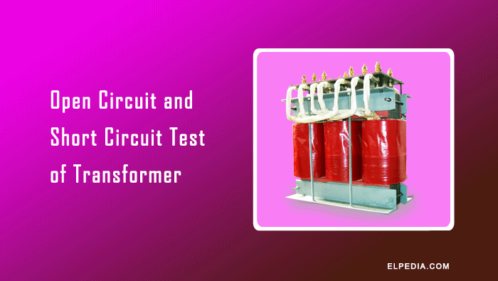
Transformers are essential components of electrical power systems, and evaluating their performance is important for efficient and reliable operation.
The open-circuit test and short-circuit test of a transformer are two standard tests used to determine its equivalent circuit parameters, losses, efficiency, and voltage regulation without conducting a direct load test.
The open-circuit test determines the core (iron) loss, no-load current, and shunt branch parameters, while the short-circuit test determines the full-load copper loss and equivalent series parameters.
These tests require relatively simple measurements of voltage, current, and power, making them practical methods for analyzing transformer performance.
In this article, you will learn the test procedures, circuit connections, working principles, formulas, and calculations involved in both tests, along with solved problems.
Open circuit test of transformer
The open-circuit test is performed to determine the core (iron) loss, no-load current, and shunt branch parameters of a transformer equivalent circuit. These parameters include the core-loss resistance (R0) and magnetizing reactance (X0).
In this test, one winding, usually the high-voltage (HV) winding, is kept open, while the rated voltage at the rated frequency is applied to the low-voltage (LV) winding.
The test circuit consists of a voltmeter to measure the applied voltage (V1), an ammeter to measure the no-load current (I0), and a wattmeter to measure the input power (W0).
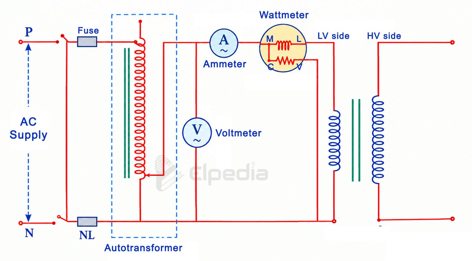
A variable autotransformer or voltage regulator may be used to adjust the applied voltage to its rated value.
Although the test can be performed by energizing either the LV or HV winding, the LV winding is generally preferred.
Applying the rated voltage to the HV winding requires a higher voltage supply, while the no-load current is relatively small and may be difficult to measure accurately.
When the rated voltage is applied to the energized winding, a small no-load current (I0) flows through it. Since the other winding is open-circuited, no current flows through that winding.
The no-load current produces the alternating magnetic flux required to establish the normal operating flux in the transformer core.
At rated voltage and frequency, the core experiences normal magnetic flux, resulting in hysteresis and eddy-current losses. The wattmeter reading (W0) therefore represents the core loss approximately:
![\[\text{Iron Loss, } P_i = \text{Input Power on no load} \]](https://elpedia.com/wp-content/ql-cache/quicklatex.com-fd858e1aafaedd4b196cf0552ee15303_l3.png "Rendered by QuickLaTeX.com")
![\[ P_i = W_0 \text{ Watts} \]](https://elpedia.com/wp-content/ql-cache/quicklatex.com-5ca60157cc44232c5bb77d2b7389bb91_l3.png "Rendered by QuickLaTeX.com")
The measured values of V1, I0, and W0 are used to determine the no-load power factor and the shunt branch parameters of the equivalent circuit.
![\[ \text{No-load power factor, }\cos\phi_0=\frac{W_0}{V_1I_0}\]](https://elpedia.com/wp-content/ql-cache/quicklatex.com-7b5eb9389b539762a4fee4a53a4d52f5_l3.png "Rendered by QuickLaTeX.com")
![\[\phi_0=cos^{-1} \frac{W_0}{V_1I_0}\]](https://elpedia.com/wp-content/ql-cache/quicklatex.com-61cb5c577a93003be76feb49ab107f69_l3.png "Rendered by QuickLaTeX.com")
![\[\text{Core loss current component, } I_w=I_0\cos\phi_0 = \frac{W_0}{V_1} \]](https://elpedia.com/wp-content/ql-cache/quicklatex.com-0d813ff72441c98b0cf35e426fc111dd_l3.png "Rendered by QuickLaTeX.com")
![\[\text{Magnetizing current component, } I_m=I_0\sin\phi_0 =\sqrt{I_0^2-I_w^2} \]](https://elpedia.com/wp-content/ql-cache/quicklatex.com-1253d70e9d0f57f6c83a138a3bb476d1_l3.png "Rendered by QuickLaTeX.com")
![\[\text{Core loss resistance, }R_0=\frac{V_1}{I_w} = \frac{V_1^2}{W_0}\]](https://elpedia.com/wp-content/ql-cache/quicklatex.com-8cc374e84a2b906c5b6335f8895a2225_l3.png "Rendered by QuickLaTeX.com")
![\[\text{Magnetizing reactance, }X_0=\frac{V_1}{I_m} \]](https://elpedia.com/wp-content/ql-cache/quicklatex.com-c682bd62a32ecdf1b00e1a544a7e8840_l3.png "Rendered by QuickLaTeX.com")
Short circuit test of transformer
The short-circuit test is conducted to determine the full-load copper loss and the equivalent resistance and reactance of a transformer referred to a specified winding, usually the metering or measurement side.
In this test, the terminals of one winding, usually the low-voltage (LV) winding, are short-circuited using a thick conductor or a suitable low-resistance connection.
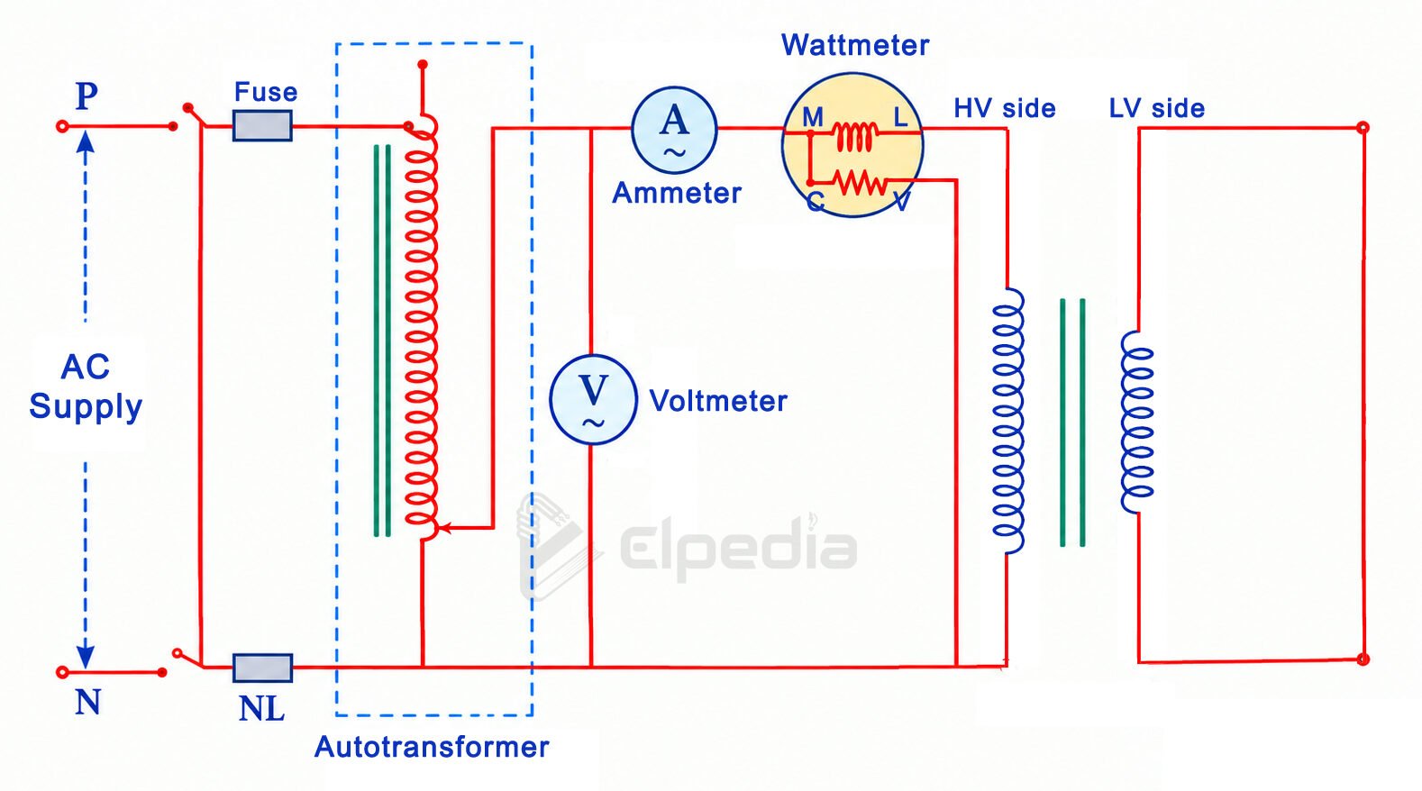
An ammeter may be connected in the circuit to measure the current flowing through the short-circuited winding.
A low adjustable voltage is applied to the other winding, usually the high-voltage (HV) winding, through a variable autotransformer.
The applied voltage is gradually increased from zero until the current reaches its rated value. Since the short-circuited winding has a very low terminal voltage, only a small voltage is required to circulate the rated current through the transformer windings.
During the short-circuit test, the applied voltage is typically about 5–10% of the rated voltage, although the actual value depends on the transformer’s percentage impedance.
Because the applied voltage is low, the magnetic flux established in the core is also small. Consequently, the iron loss is negligible compared with the copper loss.
Under these conditions, the wattmeter reading (Wsc) approximately represents the total copper loss at the test current.
When the rated current is established, the measured power corresponds to the full-load copper loss:
![\[P_{cu,\mathrm{FL}} = W_{sc} \]](https://elpedia.com/wp-content/ql-cache/quicklatex.com-93c56a5613085063a92fcc7860167e40_l3.png "Rendered by QuickLaTeX.com")
The output power is zero because the secondary winding is short-circuited and no useful load is connected. The input power is therefore mainly dissipated as copper loss in the transformer windings.
The measured voltage (Vsc), current (Isc), and power (Wsc) are used to calculate the equivalent circuit parameters referred to the energized winding:
![\[\text{Equivalent Impedance, }Z_{eq}=\frac{V_{sc}}{I_{sc}} \]](https://elpedia.com/wp-content/ql-cache/quicklatex.com-1fa3ea7bced536765ecb77c16cb4bc68_l3.png "Rendered by QuickLaTeX.com")
![\[\text{Equivalent Resistance, }R_{eq}=\frac{W_{sc}}{I_{sc}^{2}}\]](https://elpedia.com/wp-content/ql-cache/quicklatex.com-6fff8bc79e74d2b0529ebf55007dd1bf_l3.png "Rendered by QuickLaTeX.com")
![\[\text{Equivalent Reactance, }X_{eq}=\sqrt{Z_{eq}^{2}-R_{eq}^{2}}\]](https://elpedia.com/wp-content/ql-cache/quicklatex.com-a2182b21dbae5125a7aad908ced6887f_l3.png "Rendered by QuickLaTeX.com")
The above values from the short-circuit test are referred to the metering side, which is the HV winding in this test. If required, these parameters can be referred to the LV winding using the square of the transformer turns ratio.
Solved problem
The open and short-circuit tests have been conducted on 10 kVA, 120/450 V, 50 Hz transformer are: O.C. test: 120 V, 4.2 A, 80 W on the low-voltage side. S.C. test: 9.65 V, 22.2 A, 120 W with low-voltage winding short-circuited. Compute the equivalent circuit parameters referring to LV side.
Given : V1 = 120 V, V2 = 450 V, rating of transformer = 10 kVA
To find : Equivalent circuit parameters
Solution : From the OC test readings, let us compute Iw, Im, R0, X0.
![\[ \text{No-load current, } I_0 = 4.2 A \]](https://elpedia.com/wp-content/ql-cache/quicklatex.com-c51f21ed9cca5dba5a2782ec1e6c59f6_l3.png "Rendered by QuickLaTeX.com")
![\[I_w= \frac{W_0}{V_1} = \frac{80}{120} = 0.667 A\]](https://elpedia.com/wp-content/ql-cache/quicklatex.com-52ec60801da7d5130371b694928fc1a5_l3.png "Rendered by QuickLaTeX.com")
![\[ I_m =\sqrt{I_0^2-I_w^2}=\sqrt{4.2^2-0.667^2} = 17.19 A \]](https://elpedia.com/wp-content/ql-cache/quicklatex.com-4db99a706ce2d102ce1628f4a0c092e1_l3.png "Rendered by QuickLaTeX.com")
![\[R_0=\frac{V_1}{I_w} = \frac{120}{0.667}= 179.91 \, \Omega \]](https://elpedia.com/wp-content/ql-cache/quicklatex.com-9567a1f72127cc4208b79fb2b67810b6_l3.png "Rendered by QuickLaTeX.com")
![\[X_0=\frac{V_1}{I_m}=\frac{120}{17.19} = 6.98 \, \Omega \]](https://elpedia.com/wp-content/ql-cache/quicklatex.com-42b18416200ed52140ad82af64fe9f9e_l3.png "Rendered by QuickLaTeX.com")
From the SC test readings, we have to compute Ro1, X01, referring to LV side.
Equivalent impedance referred to hv side,
![\[Z_{02} = \frac{V_{sc}}{I_{sc}} = \frac{9.65}{22.2} = 0.435 \, \Omega \]](https://elpedia.com/wp-content/ql-cache/quicklatex.com-e2a879eff7a04eaf74296dc0d315ee27_l3.png "Rendered by QuickLaTeX.com")
Equivalent resistance referred to hv side,
![\[R_{02} = \frac{P_{sc}}{I_{sc}^2} = \frac{120}{22.2^2} = 0.243 \, \Omega \]](https://elpedia.com/wp-content/ql-cache/quicklatex.com-88b652f3fa7a36b3fe90a725e2c2f78b_l3.png "Rendered by QuickLaTeX.com")
Equivalent reactance referred to hv side,
![\[X_{02} = \sqrt{(Z_{02})^2 -(R_{02})^2} = \sqrt{0.435^2-0.243^2} = 0.361 \, \Omega \]](https://elpedia.com/wp-content/ql-cache/quicklatex.com-cd33255df6452946ad5130eeb2ee9157_l3.png "Rendered by QuickLaTeX.com")
Transformation ratio is given by the formula,
![\[k = \frac{V_2}{V_1} = \frac{450}{120} = 3.75 \]](https://elpedia.com/wp-content/ql-cache/quicklatex.com-5a7b8c6ebc1a27c79316ae64dbe0a81b_l3.png "Rendered by QuickLaTeX.com")
Equivalent resistance and reactance referred to LV side,
![\[R_{01} = \frac{R_{02}}{k^2} = \frac{0.243}{3.75^2} = 0.017 \,\Omega \]](https://elpedia.com/wp-content/ql-cache/quicklatex.com-72c4b0e29310ca66e96a81858f595362_l3.png "Rendered by QuickLaTeX.com")
![\[X_{01} = \frac{X_{02}}{k^2} = \frac{0.361}{3.75^2} =0.026 \,\Omega \]](https://elpedia.com/wp-content/ql-cache/quicklatex.com-b72f493f01bbea2a58f231cc9e9da84f_l3.png "Rendered by QuickLaTeX.com")