Basic Electrical Engineering Formulas with Examples
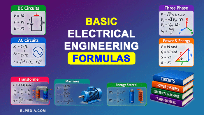
Electrical engineering relies on fundamental formulas to analyze circuits, size components, and predict system behavior. Whether you’re studying dc circuits or designing three phase power systems, having the right equations at your fingertips saves time and prevents costly errors.
This guide compiles the most important basic electrical engineering formulas with clear parameter definitions and solved examples you can apply immediately.
Electric Field, Coulomb’s Law and Gauss’s Law
The electric field concept is critical in electrical engineering for insulation design, transmission line calculations, and understanding force on charged particles.
Coulomb’s Law: It gives the force between two point charges. It is measured in Newton (N).
![\[ \boxed{F = \frac{1}{4\pi \varepsilon} \· \frac{Q_1 Q_2}{r^2}}\]](https://elpedia.com/wp-content/ql-cache/quicklatex.com-40318217406ff870a72d0499c692aa94_l3.png "Rendered by QuickLaTeX.com")
For a material, the permittivity is given by,
![\[ \boxed{\varepsilon = \varepsilon_0 \varepsilon_r} \]](https://elpedia.com/wp-content/ql-cache/quicklatex.com-fdb121a1774620421c8c070f8ed20e1b_l3.png "Rendered by QuickLaTeX.com")
where εr is the relative permittivity (dielectric constant) of the material and ε0 is the permittivity of the free space or air and is given by,
![\[ \boxed{\varepsilon_0 = 8.854 \times 10^{-12} F/m} \]](https://elpedia.com/wp-content/ql-cache/quicklatex.com-1410470f323d0482154e11341b7eb42c_l3.png "Rendered by QuickLaTeX.com")
Electric field intensity: Electric field intensity at a point is defined as the force experienced by a unit positive test charge placed at that point in an electric field.
![\[\boxed{E = \frac{F}{Q_0} }\]](https://elpedia.com/wp-content/ql-cache/quicklatex.com-1152f9f392ab01423a223fd36f1dcfd3_l3.png "Rendered by QuickLaTeX.com")
For a point charge Q, the electric field intensity at a distance r is given by,
![\[\boxed{E = \frac{1}{4\pi \varepsilon} \· \frac{Q}{r^2}} \]](https://elpedia.com/wp-content/ql-cache/quicklatex.com-e79c56598dc36d6bedd49c3927ab70b1_l3.png "Rendered by QuickLaTeX.com")
In free space or air, approximately,
![\[\boxed{E = \frac{9 \times 10^9 \, Q}{r^2}} \]](https://elpedia.com/wp-content/ql-cache/quicklatex.com-f01258fee16addc359f21d39c9c14a74_l3.png "Rendered by QuickLaTeX.com")
Electric flux: It is obtained from the surface integral of the electric field over a closed surface.
![\[\boxed{\Phi_e = \iint_S E.dA}\]](https://elpedia.com/wp-content/ql-cache/quicklatex.com-80515dd65a10092115103bf28298d4fc_l3.png "Rendered by QuickLaTeX.com")
Gauss’s Law: The total electric flux through any closed surface is equal to the net electric charge enclosed by the surface divided by the permittivity (ε) of the medium.
![\[\boxed{\Phi_e = \frac{Q_{\text{enclosed}}}{\varepsilon}} \]](https://elpedia.com/wp-content/ql-cache/quicklatex.com-fc74a3d2370b298a1472cb59cbb8fe27_l3.png "Rendered by QuickLaTeX.com")
Example:
Find the electric field strength at a distance of 0.1 m from a point charge of 1 μC in air. (ε₀ = 8.854 × 10⁻¹² F/m):
The electric field due to a point charge is given by
![\[E = \frac{9 \times 10^9 \, Q}{r^2} \]](https://elpedia.com/wp-content/ql-cache/quicklatex.com-803f28bc8761965b58c8238d35f9da43_l3.png "Rendered by QuickLaTeX.com")
![\[E=\frac{(9\times10^9)(1\times10^{-6})}{(0.1)^2} \]](https://elpedia.com/wp-content/ql-cache/quicklatex.com-50077c7d13ae30683013926707b0455a_l3.png "Rendered by QuickLaTeX.com")
![\[E=9\times10^5\ \text{N/C} = 900\ \text{kN/C}}\]](https://elpedia.com/wp-content/ql-cache/quicklatex.com-a8bd91afeee0e3748421950f7c192c1e_l3.png "Rendered by QuickLaTeX.com")
The field is directed away from the charge because the charge is positive.
Basic Electrical Quantities and Ohm’s Law
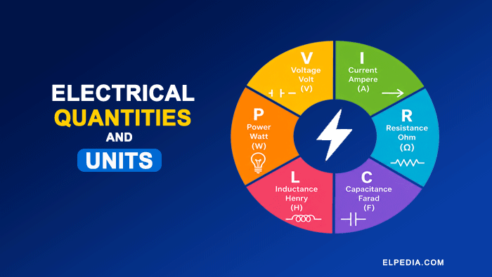
Electric charge, electric current, potential difference, and electrical resistance are the building blocks of basic electrical engineering. Every circuit analysis problem starts with these quantities.
Charge (Q): Electric charge is measured in coulombs (C).
![\[ \boxed{Q = ne} \]](https://elpedia.com/wp-content/ql-cache/quicklatex.com-2fc2c3d4b6f72198eee36d272d2a9205_l3.png "Rendered by QuickLaTeX.com")
where an electron (e) carries a charge of −1.6 × 10⁻¹⁹ C. Electric charge is quantized as integral multiples of elementary charge, and electric charge is carried by electrons and protons.
Current (I): It is the rate of flow of electric charge, given by the below given formula. current is measured in amperes (A).
![\[ \boxed {I = \frac{Q}{t} } \]](https://elpedia.com/wp-content/ql-cache/quicklatex.com-c4db36a371f18966afd23d1f754531ce_l3.png "Rendered by QuickLaTeX.com")
Voltage (V): It is the work done in moving a unit charge, measured in volts (V).
![\[\boxed{V = \frac{\text{Work done}}{\text{Charge}} =\frac{W}{Q} } \]](https://elpedia.com/wp-content/ql-cache/quicklatex.com-eabf90903db48f9c9dec06e16b7b1da1_l3.png "Rendered by QuickLaTeX.com")
Voltage is directly proportional to current in a conductor (for ohmic material).
Resistance (R): It is the opposition for the flow of electric current through a conductor. Resistance is denoted by the symbol R and is measured in Ohms (Ω). Resistance is calculated using,
![\[ \boxed {R = \frac{\rho \ell }{A}} \]](https://elpedia.com/wp-content/ql-cache/quicklatex.com-b183bd3a2b7dc128e32470e92053c1dc_l3.png "Rendered by QuickLaTeX.com")
where ρ is the resistivity is a material property opposing current flow.
Conductance: Conductance is the reciprocal of resistance, and is measured in siemens. It is given by the formula
![\[ \boxed{G = \frac{1}{R}} \]](https://elpedia.com/wp-content/ql-cache/quicklatex.com-359498090e5be6a4ce8aad013ae1c2ce_l3.png "Rendered by QuickLaTeX.com")
Ohm’s Law gives the relation between the voltage, current and resistance, given by the formula,
![\[ \boxed{V = IR} \]](https://elpedia.com/wp-content/ql-cache/quicklatex.com-30b5d29bc191af8de6e7325f90d52c64_l3.png "Rendered by QuickLaTeX.com")
It applies to ohmic conductors under constant temperature. The formula can be rearranged to find the value of current and resistance, as shown below
![\[ \boxed{\text{Current, I} = \frac{V}{R}} \]](https://elpedia.com/wp-content/ql-cache/quicklatex.com-fcb306c7d213f843eb7ec49bddb59069_l3.png "Rendered by QuickLaTeX.com")
![\[ \boxed{\text{Resistance, R} = \frac{V}{I}} \]](https://elpedia.com/wp-content/ql-cache/quicklatex.com-8778e39fe0e84035b03e5f8416797ac1_l3.png "Rendered by QuickLaTeX.com")
Electric Power:
Power is the rate at which energy is consumed or supplied. It is given by the physical formula,
![\[ \boxed{P=\frac{dW}{dt}} \]](https://elpedia.com/wp-content/ql-cache/quicklatex.com-08beca3c13d174e122eeedd43890cab1_l3.png "Rendered by QuickLaTeX.com")
For DC Supply, the electrical power is given by the below formula. It is measured in watts (W)
![\[ \boxed{P = VI} \]](https://elpedia.com/wp-content/ql-cache/quicklatex.com-020c193af3fb57d148285e72d74d4a20_l3.png "Rendered by QuickLaTeX.com")
By using ohm’s law, the power can be modified as below,
![\[\boxed{ P = I^2R} \]](https://elpedia.com/wp-content/ql-cache/quicklatex.com-fb71f1df1ec0673112472b7e1de1e397_l3.png "Rendered by QuickLaTeX.com")
![\[\boxed{ P = \frac{V^2}{R} } \]](https://elpedia.com/wp-content/ql-cache/quicklatex.com-eb6ef3076de1e902127adf15f0e9a104_l3.png "Rendered by QuickLaTeX.com")
Example
Consider a copper wire which has the resistivity (ρ) of 1.68 × 10⁻⁸ Ω·m. It is 50 m long with cross-section 2.5 mm². Assume the applied voltage as 5 V. Calculate its resistance and current flowing through it.
Using the resistance formula,
![\[R=\frac{\rho\ell}{A} \]](https://elpedia.com/wp-content/ql-cache/quicklatex.com-cc63c0d2a14b0339dcde52bcf01706c4_l3.png "Rendered by QuickLaTeX.com")
![\[R=\frac{(1.68\times10^{-8})(50)}{2.5\times10^{-6}} \]](https://elpedia.com/wp-content/ql-cache/quicklatex.com-529ab723a9fdbd706d62451450765888_l3.png "Rendered by QuickLaTeX.com")
![\[ R=0.336 \, \Omega \]](https://elpedia.com/wp-content/ql-cache/quicklatex.com-730bdc042f4b9e5d4101ea83eff8089a_l3.png "Rendered by QuickLaTeX.com")
Using Ohm’s law,
![\[I=\frac{V}{R}\]](https://elpedia.com/wp-content/ql-cache/quicklatex.com-d47adf576fd8fb61c6e0d0d8e24490ce_l3.png "Rendered by QuickLaTeX.com")
![\[I=\frac{5}{0.336} = 14.88\ \text{A} \]](https://elpedia.com/wp-content/ql-cache/quicklatex.com-eeaf1c647f22c68c30eabd41cb60ae4c_l3.png "Rendered by QuickLaTeX.com")
DC Circuits formulas
Understanding series and parallel connections plus Kirchhoff’s laws is essential for analyzing any electrical circuit in dc circuits.
In a series circuit, electrical elements are connected one after another, so the same current flows through all elements.
![\[ \boxed{R_{\text{total}}=R_1+R_2+\cdots+R_n} \]](https://elpedia.com/wp-content/ql-cache/quicklatex.com-3e9ca6c3117babff58229952ccc30236_l3.png "Rendered by QuickLaTeX.com")
The voltage is divided among the resistors according to their resistance. The voltage across resistor (R1) is:
![\[\boxed{V_1=V_{\text{total}} \, \frac{R_1}{R_{\text{total}}}} \]](https://elpedia.com/wp-content/ql-cache/quicklatex.com-b322b26d370eff5162678167a7937ab1_l3.png "Rendered by QuickLaTeX.com")
In a parallel circuit, electrical elements are connected across the same two nodes. Therefore, the voltage is the same across each branch, while the current divides among the branches.
![\[\boxed{\frac{1}{R_{\text{total}}}= \frac{1}{R_1}+\frac{1}{R_2}+\cdots+\frac{1}{R_n}}\]](https://elpedia.com/wp-content/ql-cache/quicklatex.com-042d11f37fc77fb7cc7ab62cb004e4c4_l3.png "Rendered by QuickLaTeX.com")
For two resistors in parallel:
![\[\boxed{R_{\text{total}}=\frac{R_1R_2}{R_1+R_2}} \]](https://elpedia.com/wp-content/ql-cache/quicklatex.com-24a107a512e7fe0a510efb1cec63f2a7_l3.png "Rendered by QuickLaTeX.com")
Kirchhoff’s Current Law states that the total current entering a junction is equal to the total current leaving the junction.
![\[\boxed{\sum I_{\text{in}}=\sum I_{\text{out}}} \]](https://elpedia.com/wp-content/ql-cache/quicklatex.com-d241d066d88863a9d86254cd588b0034_l3.png "Rendered by QuickLaTeX.com")
KCL is based on the principle of conservation of electric charge.
Kirchhoff’s Voltage Law states that the algebraic sum of all voltages around any closed loop is zero.
![\[\boxed{\sum V=0} \]](https://elpedia.com/wp-content/ql-cache/quicklatex.com-70fbfa5e8bed5667cc69fc7442f20e42_l3.png "Rendered by QuickLaTeX.com")
KVL is based on the principle of conservation of energy.
Example
Consider a 12 V battery connected to two resistors, R1 = 4 Ω and R2 = 6 Ω, in series. This series combination is connected in parallel with R3 = 10 Ω. Find the total resistance, total current and current in each parallel branch.
Since 4 Ω and 6 Ω are connected in series, the total series resistance is given by,
![\[ R_s=R_1+R_2=4+6=10 \,\Omega \]](https://elpedia.com/wp-content/ql-cache/quicklatex.com-0114fccef3071f4d3b6e5d7afd2f2676_l3.png "Rendered by QuickLaTeX.com")
This series combination is in parallel with R3 = 10 Ω, the total resistance is obtained as,
![\[ R_{\text{total}}= \frac{R_3\times R_s}{R_3+R_s} \]](https://elpedia.com/wp-content/ql-cache/quicklatex.com-f9fd4e112cc4a9eccd6f96ae388aeaf4_l3.png "Rendered by QuickLaTeX.com")
![\[ R_{\text{total}}= \frac{10\times10}{10+10} =5 \,\Omega \]](https://elpedia.com/wp-content/ql-cache/quicklatex.com-044d23f8f69789f25c988cb23f9390aa_l3.png "Rendered by QuickLaTeX.com")
The total current is calculated as,
![\[I_{\text{total}}= \frac{V}{R_{\text{total}}} =\frac{12}{5} = 2.4 \,A \]](https://elpedia.com/wp-content/ql-cache/quicklatex.com-43d23f3ace5c1f6197c85a894d0cd111_l3.png "Rendered by QuickLaTeX.com")
Since both parallel branches have the same resistance of 10 Ω,
![\[ I_1=I_2=\frac{V}{R}=\frac{12}{10}=1.2 \, A \]](https://elpedia.com/wp-content/ql-cache/quicklatex.com-a7c19872a29e85eaa8771e7f027dee3d_l3.png "Rendered by QuickLaTeX.com")
AC Fundamental formulas
Alternating current (AC) is characterized by its frequency (f), measured in hertz (Hz). Frequency represents the number of complete cycles occurring per second. The relationship between frequency and time period is,
![\[\boxed{f=\frac{1}{T}} \]](https://elpedia.com/wp-content/ql-cache/quicklatex.com-7e99c66b415ee0138f9bd71453f7e7c1_l3.png "Rendered by QuickLaTeX.com")
where (T) is the time period, or the time required to complete one cycle.
The angular frequency is given by,
![\[ \boxed{\omega=2\pi f} \]](https://elpedia.com/wp-content/ql-cache/quicklatex.com-0f6f20538b2a7c946060ba71161b3431_l3.png "Rendered by QuickLaTeX.com")
where ω is measured in radians per second (rad/s).
Inductive reactance (XL) is the opposition offered by an inductor to the flow of alternating current. It is given by the formula,
![\[\boxed{X_L=2\pi fL=\omega L} \]](https://elpedia.com/wp-content/ql-cache/quicklatex.com-08196d97434d18019f905ff7cbb37b32_l3.png "Rendered by QuickLaTeX.com")
The inductive reactance increases with frequency. Inductance (L) is measured in henrys (H).
Capacitive reactance (XC) is the opposition offered by a capacitor to the flow of alternating current. It is given by
![\[ \boxed{X_C=\frac{1}{2\pi fC}=\frac{1}{\omega C}} \]](https://elpedia.com/wp-content/ql-cache/quicklatex.com-91c61d5b9b5dab8e75b4ebeaa5fb0b82_l3.png "Rendered by QuickLaTeX.com")
Unlike inductive reactance, capacitive reactance decreases as frequency increases. Capacitance (C) is measured in farads (F).
Impedance (Z) is the total opposition offered by an AC circuit to the flow of current. It combines the effects of resistance and reactance and is measured in ohms (Ω).
For a series RLC circuit, the magnitude of impedance is,
![\[ \boxed{Z=\sqrt{R^2+X^2}} \]](https://elpedia.com/wp-content/ql-cache/quicklatex.com-2dad9ccb59c9b90ab6614fdc1271d2a6_l3.png "Rendered by QuickLaTeX.com")
![\[ \boxed{Z=\sqrt{R^2+(X_L-X_C)^2}} \]](https://elpedia.com/wp-content/ql-cache/quicklatex.com-71531ca760270732e581182cccc54067_l3.png "Rendered by QuickLaTeX.com")
For a purely resistive AC circuit, the reactance is zero, so Z = R.
In a series RLC circuit, resonance occurs when the inductive reactance equals the capacitive reactance,
![\[X_L=X_C \]](https://elpedia.com/wp-content/ql-cache/quicklatex.com-720f1657fba57861f7edbccce3735cca_l3.png "Rendered by QuickLaTeX.com")
The resonant frequency is,
![\[\boxed{f_0=\frac{1}{2\pi\sqrt{LC}}} \]](https://elpedia.com/wp-content/ql-cache/quicklatex.com-fa5cace592590bdf3d88dbe2ad388e7a_l3.png "Rendered by QuickLaTeX.com")
At resonance, the net reactance is zero and the circuit has only resistance (Z = R). So the circuit impedance becomes minimum. Therefore, for a given supply voltage, the current reaches its maximum value.
AC Ohm’s Law : Ohm’s law for AC circuits is expressed using impedance,
![\[ \boxed{V=IZ} \]](https://elpedia.com/wp-content/ql-cache/quicklatex.com-065d16a58af6ab5d56c9631c3d726478_l3.png "Rendered by QuickLaTeX.com")
In phasor form:
![\[ \boxed{\overline{V}=\overline{I}Z} \]](https://elpedia.com/wp-content/ql-cache/quicklatex.com-0e0b5f12861247fff3797ba7a3b84442_l3.png "Rendered by QuickLaTeX.com")
Example:
A 230 V, 50 Hz single-phase AC supply feeds a load that draws 10 A at a power factor of 0.8 lagging. Determine the active power, reactive power, and apparent power.
Given:
![\[ V=230\text{ V},\qquad I=10\text{ A},\qquad \cos\phi=0.8 \]](https://elpedia.com/wp-content/ql-cache/quicklatex.com-22a3613dae20ee9d8791455f03f7f437_l3.png "Rendered by QuickLaTeX.com")
![\[\text{Active Power, P}=VI\cos\phi \]](https://elpedia.com/wp-content/ql-cache/quicklatex.com-fe05753b37220952c0a775c29104a30d_l3.png "Rendered by QuickLaTeX.com")
![\[P=230\times10\times0.8 =1840\text{ W} \]](https://elpedia.com/wp-content/ql-cache/quicklatex.com-2e4052f9009ba0ae63604fc5e8588b7c_l3.png "Rendered by QuickLaTeX.com")
![\[\text{Reactive Power, Q}=VI\sin\phi \]](https://elpedia.com/wp-content/ql-cache/quicklatex.com-9aaa8008f28e0b3faa349ccedbcc202c_l3.png "Rendered by QuickLaTeX.com")
![\[ Q=230\times10\times0.6 =1380\text{ VAR} \]](https://elpedia.com/wp-content/ql-cache/quicklatex.com-cc7f3fba507cf416a0afe3754603115f_l3.png "Rendered by QuickLaTeX.com")
Because the power factor is lagging, the reactive power is inductive.
![\[ \text{Apparent Power, S}=VI =230\times10 =2300\text{ VA} \]](https://elpedia.com/wp-content/ql-cache/quicklatex.com-718743e82aebabbf5424c37b4de80fd8_l3.png "Rendered by QuickLaTeX.com")
Therefore, the load consumes 1.84 kW of active power, 1.38 kVAR of reactive power, and has an apparent power of 2.3 kVA.
Single-Phase and Three-Phase AC Power Formulas
Single-phase AC systems are commonly used for residential applications and small electrical loads, whereas three-phase AC systems are widely used for power generation, transmission, distribution, and industrial loads such as large motors. Three-phase systems provide more efficient and balanced power delivery for high-power applications.
Single-phase AC power
In a single-phase AC circuit, electrical power is classified into active power, reactive power, and apparent power.
Active power is the actual power consumed or converted into useful work by the load. It is measured in watts (W).
![\[ \boxed{P=VI\cos\phi} \]](https://elpedia.com/wp-content/ql-cache/quicklatex.com-1089c3d43d91841d97f39b53b4ace060_l3.png "Rendered by QuickLaTeX.com")
Reactive power is the power that alternately flows between the source and reactive elements such as inductors and capacitors. It is measured in volt-amperes reactive (VAR).
![\[ \boxed{Q=VI\sin\phi} \]](https://elpedia.com/wp-content/ql-cache/quicklatex.com-6d77e0bb87d0ee65e883373c156512b8_l3.png "Rendered by QuickLaTeX.com")
Apparent power is the product of the RMS voltage and RMS current. It is measured in volt-amperes (VA).
![\[ \boxed{S=VI} \]](https://elpedia.com/wp-content/ql-cache/quicklatex.com-e56819cc30a2a5c7bda154c70257c7a7_l3.png "Rendered by QuickLaTeX.com")
The relationship among active, reactive, and apparent power is:
![\[ \boxed{S^2=P^2+Q^2} \]](https://elpedia.com/wp-content/ql-cache/quicklatex.com-d294bf5e8b2a7ff2baecfc8dda4b2ae7_l3.png "Rendered by QuickLaTeX.com")
Power factor (pf) is the ratio of active power to apparent power.
![\[\boxed{\text{pf}=\cos\phi=\frac{P}{S}} \]](https://elpedia.com/wp-content/ql-cache/quicklatex.com-30e73f976da5bbf40b201097d0b0d4c4_l3.png "Rendered by QuickLaTeX.com")
For an inductive load, the power factor is lagging, while for a capacitive load, it is leading.
These AC circuit formulas are fundamental for analyzing single-phase and three-phase AC circuits, including circuits containing resistors, inductors, and capacitors.
These impedance formulas and concepts apply across all phase ac circuits.
Three Phase System
In a balanced three-phase system with a star (Y) connection, the relationship between line and phase quantities is:
![\[ \boxed{V_L=\sqrt{3} \,V_{Ph}} \]](https://elpedia.com/wp-content/ql-cache/quicklatex.com-e0b0cbb222b05b3699255d748255181f_l3.png "Rendered by QuickLaTeX.com")
![\[ \boxed{I_L=I_{Ph}} \]](https://elpedia.com/wp-content/ql-cache/quicklatex.com-1605abaa6d8a509fff918386882bed83_l3.png "Rendered by QuickLaTeX.com")
where VL and IL are the line voltage and line current, while VPh and IPh are the phase voltage and phase current.
For a balanced three-phase system with a delta (Δ) connection:
![\[\boxed{V_L=V_{Ph}}\]](https://elpedia.com/wp-content/ql-cache/quicklatex.com-b8ca15d975a8c647a58136ed4047ae18_l3.png "Rendered by QuickLaTeX.com")
![\[\boxed{I_L=\sqrt{3} \,I_{Ph}} \]](https://elpedia.com/wp-content/ql-cache/quicklatex.com-1fe38a19290482bc02f0bf99173a9115_l3.png "Rendered by QuickLaTeX.com")
Three-Phase AC Power
The total active power in a balanced three-phase AC circuit is,
![\[\boxed{P=\sqrt{3} \,V_LI_L\cos\phi} \]](https://elpedia.com/wp-content/ql-cache/quicklatex.com-ad25c917648cb9cfa051cfa725860938_l3.png "Rendered by QuickLaTeX.com")
Alternatively, using phase quantities:
![\[\boxed{P=3V_{Ph}I_{Ph}\cos\phi} \]](https://elpedia.com/wp-content/ql-cache/quicklatex.com-189cf1b565801f9aa1750d177fb23d73_l3.png "Rendered by QuickLaTeX.com")
Similarly, the total reactive and apparent powers are:
![\[ \boxed{Q=\sqrt{3} \, V_LI_L\sin\phi} \]](https://elpedia.com/wp-content/ql-cache/quicklatex.com-e872042d7a6971e37cddc88652e9cf89_l3.png "Rendered by QuickLaTeX.com")
![\[\boxed{S=\sqrt{3}V_LI_L} \]](https://elpedia.com/wp-content/ql-cache/quicklatex.com-2de1f932c219eeb0e9064e0d5bc6ae2e_l3.png "Rendered by QuickLaTeX.com")
These formulas are applicable to balanced three-phase systems, regardless of whether the load is connected in star or delta, provided the corresponding line and phase relationships are used correctly.
AC Electrical Energy : Electrical energy consumed by an AC load is calculated from,
![\[\boxed{E=Pt} \]](https://elpedia.com/wp-content/ql-cache/quicklatex.com-d341dd045450a12b4bcd147e39f3ae11_l3.png "Rendered by QuickLaTeX.com")
If power is expressed in kilowatts and time in hours, the resulting energy is in kilowatt-hours:
![\[\boxed{E(\text{kWh})=P(\text{kW})\times t(\text{h})} \]](https://elpedia.com/wp-content/ql-cache/quicklatex.com-b6609a7d55b5759a3ad3e25a321a3099_l3.png "Rendered by QuickLaTeX.com")
The kilowatt-hour (kWh) is the commonly used unit for measuring electrical energy consumption.
Example:
A three-phase motor is supplied from a 400 V line-to-line supply and draws 20 A at a power factor of 0.85. Determine the active power consumed by the motor.
Given:
![\[ V_L=400\text{ V}\,\qquad I_L=20\text{ A}\,\qquad \cos\phi=0.85 \]](https://elpedia.com/wp-content/ql-cache/quicklatex.com-db6f252d4c0a592efded72621b3847df_l3.png "Rendered by QuickLaTeX.com")
Using the three-phase power formula:
![\[ P=\sqrt{3}V_LI_L\cos\phi \]](https://elpedia.com/wp-content/ql-cache/quicklatex.com-c8d81cd803ba63ae9c1b61a2c466bae5_l3.png "Rendered by QuickLaTeX.com")
![\[P=\sqrt{3}\times400\times20\times0.85 \]](https://elpedia.com/wp-content/ql-cache/quicklatex.com-da7c49ddcf9baa3fed7f6cea2ded1a24_l3.png "Rendered by QuickLaTeX.com")
![\[P = 11,778\text{ W} = 11.78\text{ kW}\]](https://elpedia.com/wp-content/ql-cache/quicklatex.com-c31c1eb043757d995b54c5e5298bc577_l3.png "Rendered by QuickLaTeX.com")
Energy Storage Elements
A capacitor stores electric charge in an electrostatic field, while inductors store energy in a magnetic field. Both are critical electrical components in every electrical system.
Capacitor formulas:
Capacitance is defined as
![\[ \boxed{C = \frac{Q}{V}} \]](https://elpedia.com/wp-content/ql-cache/quicklatex.com-17cb2a91d0105f0defb4922741a8a7ac_l3.png "Rendered by QuickLaTeX.com")
The unit of capacitance is microfarad (μF). Charge Q is calculated as
![\[ \boxed{Q = C \times V} \]](https://elpedia.com/wp-content/ql-cache/quicklatex.com-d9c6ffd28a91e61048c5059df3dde80d_l3.png "Rendered by QuickLaTeX.com")
For a parallel-plate capacitor, capacitance can be expressed as
![\[ \boxed{C = \frac{\varepsilon A}{d}} \]](https://elpedia.com/wp-content/ql-cache/quicklatex.com-06e85536897b77f3b49926fa124608e5_l3.png "Rendered by QuickLaTeX.com")
Energy stored in a capacitor is calculated from the formula,
![\[ \boxed{W_C = \frac{1}{2}CV^2}\]](https://elpedia.com/wp-content/ql-cache/quicklatex.com-1c30b25d94d40a7c667ba70e16c4d01f_l3.png "Rendered by QuickLaTeX.com")
Inductor formulas:
The formula for inductance is
![\[ \boxed{L = \frac{N\phi}{I}}\]](https://elpedia.com/wp-content/ql-cache/quicklatex.com-2ad9427888fa533ca0eac4901473743d_l3.png "Rendered by QuickLaTeX.com")
Inductance is the property that stores energy in a magnetic field. Inductance relates magnetic flux linkage to current.
Induced EMF is given by the formula,
![\[\boxed{ e_L = −L \frac{di}{dt}} \]](https://elpedia.com/wp-content/ql-cache/quicklatex.com-927a65e6b184e7600a404ba3d0f26917_l3.png "Rendered by QuickLaTeX.com")
Energy stored in the inductor is given by,
![\[ \boxed{ W_L = \frac{1}{2} LI^2 }\]](https://elpedia.com/wp-content/ql-cache/quicklatex.com-f6f60c0931217598212ec23ef5a333bc_l3.png "Rendered by QuickLaTeX.com")
Magnetic circuit formulas:
Reluctance is expressed as,
![\[ \boxed{ \mathcal{R} = \frac{\ell}{\mu A} }\]](https://elpedia.com/wp-content/ql-cache/quicklatex.com-5c2636f9c4f06beb059445bae9b526aa_l3.png "Rendered by QuickLaTeX.com")
Magnetic flux is calculated from the formula,
![\[ \boxed{\phi = \frac{NI}{\mathcal{R}} }\]](https://elpedia.com/wp-content/ql-cache/quicklatex.com-55b7588e23558de34e0a522c4099fcfa_l3.png "Rendered by QuickLaTeX.com")
Magnetic field intensity is determined from the formula,
![\[ \boxed{ H = \frac{NI}{\ell} }\]](https://elpedia.com/wp-content/ql-cache/quicklatex.com-641c07338a3a9240f454b48861e36616_l3.png "Rendered by QuickLaTeX.com")
Flux density is obtained from the formula,
![\[ \boxed{ B = \frac{\phi}{A} = \mu H } \]](https://elpedia.com/wp-content/ql-cache/quicklatex.com-86cbcaee0402409d7dff866ed07255d4_l3.png "Rendered by QuickLaTeX.com")
Example
Calculate the energy in a 100 μF capacitor at 50 V and calculate the energy in a 10 mH inductor at 5 A.
Energy stored in a capacitor is given by,
![\[ W_C = \frac{1}{2}CV^2\]](https://elpedia.com/wp-content/ql-cache/quicklatex.com-09743e4918c68276b94fd3aacd35bfe0_l3.png "Rendered by QuickLaTeX.com")
![\[ W_C = \frac{1}{2}\times 100 \times 50^2 = 0.125 \, J\]](https://elpedia.com/wp-content/ql-cache/quicklatex.com-035a3187adcbb60300e2b2d57d0c1f37_l3.png "Rendered by QuickLaTeX.com")
Energy stored in a inductor is given by,
![\[ W_L = \frac{1}{2} LI^2 \]](https://elpedia.com/wp-content/ql-cache/quicklatex.com-ceb4cc47502236eda46a051fd4966dfb_l3.png "Rendered by QuickLaTeX.com")
![\[ W_L = \frac{1}{2} \times 10 \times 10^{-3} \times 5^2 = 0.125 \, J \]](https://elpedia.com/wp-content/ql-cache/quicklatex.com-6d19fc813a5aa5f07c24374e023cb0d1_l3.png "Rendered by QuickLaTeX.com")
Electrical Machine Formulas
Faraday’s law of electromagnetic induction is the fundamental principle behind the operation of many electrical machines, including generators, transformers, and induction motors.
Faraday’s Law: It states that an electromotive force (EMF) is induced in a coil (N turns) whenever the magnetic flux (ϕ) linking the coil changes with time (t).
![\[ \boxed{e = -N \frac{d\phi}{dt} }\]](https://elpedia.com/wp-content/ql-cache/quicklatex.com-28843111e69430cd43955ceae2a62874_l3.png "Rendered by QuickLaTeX.com")
Transformer essential formulas:
EMF equation of a transformer is given by the formula,
![\[ \boxed {E = 4.44 f \phi_m N } \]](https://elpedia.com/wp-content/ql-cache/quicklatex.com-a7f5fec25e7cdb97ba4e615abce56bbd_l3.png "Rendered by QuickLaTeX.com")
Transformation ratio relates the primary and secondary voltages and currents by the formula,
![\[ \boxed{ k = \frac{N_2}{N_1} = \frac{V_2}{V_1} = \frac{I_1}{I_2} } \]](https://elpedia.com/wp-content/ql-cache/quicklatex.com-b6f25c6dea925847e9cde4e82554aa09_l3.png "Rendered by QuickLaTeX.com")
Electrical efficiency can be calculated as the ratio of output power to input power.
![\[ \boxed{ \eta = \frac{P_{\text{out}}}{P_{\text{in}}}} \]](https://elpedia.com/wp-content/ql-cache/quicklatex.com-2cb2de5c52125f92ce812551423d92f9_l3.png "Rendered by QuickLaTeX.com")
Voltage regulation of a transformer is calculated from the formula,
![\[ \boxed {\text{Voltage Regulation} = \frac{V_{\text{no-load}} - V_{\text{full-load}}}{V_{\text{full-load}}} \times 100 \% } \]](https://elpedia.com/wp-content/ql-cache/quicklatex.com-1e850445931b629d5cdb0b9b03a9439e_l3.png "Rendered by QuickLaTeX.com")
DC machine formulas:
EMF generated by the DC generator is given by,
![\[ \boxed{E = \frac{P\phi ZN}{60A} } \]](https://elpedia.com/wp-content/ql-cache/quicklatex.com-da49925f6610be31650c152dfa9c0e3e_l3.png "Rendered by QuickLaTeX.com")
where P = poles, ϕ = flux/pole, Z = armature conductors, N = speed (rpm), A = parallel paths
Torque of a DC Motor is given by the formula,
![\[ \boxed{T = \frac{P\phi ZI_a}{2\pi A}}\]](https://elpedia.com/wp-content/ql-cache/quicklatex.com-aa6e732d8dfe9dbe065947eeed0ff986_l3.png "Rendered by QuickLaTeX.com")
It can be simplified as
![\[ \boxed{ T \propto \phi I_a }\]](https://elpedia.com/wp-content/ql-cache/quicklatex.com-893d4b8a64d13749bc3b81c55cdb32de_l3.png "Rendered by QuickLaTeX.com")
Speed-voltage relation is defined by the formula,
![\[ \boxed{ N \propto \frac{(V - I_a R_a)}{\phi} } \]](https://elpedia.com/wp-content/ql-cache/quicklatex.com-48b93fc4b9bb3c20d51fe55b9a7fa748_l3.png "Rendered by QuickLaTeX.com")
Hysteresis Loss is the loss that occurs due to continuous magnetic reversal. It is expressed as,
![\[\boxed{P_{hy} = \eta \,B_{\text{max}}^{1.6}\, f\, v }\]](https://elpedia.com/wp-content/ql-cache/quicklatex.com-4a1e9635f3faeeebe6290e58a350310d_l3.png "Rendered by QuickLaTeX.com")
Eddy current loss is the circulating current in the electric machine, expressed as,
![\[\boxed{P_e =K_e B_{\text{max}}^2 \,f^2\, v\,t^2 }\]](https://elpedia.com/wp-content/ql-cache/quicklatex.com-939789a977ec628d4d5ccfb8b8f7d50a_l3.png "Rendered by QuickLaTeX.com")
Induction motor formulas:
Synchronous speed is determined from the formula,
![\[ \boxed{N_s = \frac{120f}{P} }\]](https://elpedia.com/wp-content/ql-cache/quicklatex.com-0d29446e9c0ac77f5d179032879f8c64_l3.png "Rendered by QuickLaTeX.com")
Slip of a induction motor is obtained from,
![\[ \boxed{s = \frac{N_s - N}{N_s} }\]](https://elpedia.com/wp-content/ql-cache/quicklatex.com-6247f8e14e6e4a2ff8d125141f519f26_l3.png "Rendered by QuickLaTeX.com")
Mechanical power of the induction motor is given by,
![\[\boxed{ P_m = \frac{2\phi NT}{60} }\]](https://elpedia.com/wp-content/ql-cache/quicklatex.com-b3e4328d6fe179c59875b19ffbc8c334_l3.png "Rendered by QuickLaTeX.com")
Example
A 4-pole, 50 Hz induction motor operates at a rotor speed of 1440 rpm. Determine the synchronous speed and slip.
The synchronous speed is given by the formula,
![\[N_s=\frac{120f}{P} \]](https://elpedia.com/wp-content/ql-cache/quicklatex.com-6ef5bc820bd89340aaf6395387a9e96a_l3.png "Rendered by QuickLaTeX.com")
![\[N_s =\frac{120\times 50}{4} = 1500 \text{ rpm} \]](https://elpedia.com/wp-content/ql-cache/quicklatex.com-fc309573b137fc061535d6b8427c9854_l3.png "Rendered by QuickLaTeX.com")
The slip is given by,
![\[ s=\frac{N_s-N}{N_s} =\frac{1500-1440}{1500} =0.04 \]](https://elpedia.com/wp-content/ql-cache/quicklatex.com-4fe4a15d6a795da67aff5fc8dde064f6_l3.png "Rendered by QuickLaTeX.com")
![\[ s=4 \% \]](https://elpedia.com/wp-content/ql-cache/quicklatex.com-ee939c48a2e027b72c527798d8a6fa37_l3.png "Rendered by QuickLaTeX.com")
Power factor correction formulas
Required reactive power:
![\[ \boxed{Q_c = P(tan \phi_1 - tan\phi_2)} \]](https://elpedia.com/wp-content/ql-cache/quicklatex.com-54bc69825ba02ae64c81c315902e1956_l3.png "Rendered by QuickLaTeX.com")
For a single-phase capacitor connected across an AC supply, the capacitor reactive power is determined from the formula,
![\[ \boxed{ Q_c = V^2 \omega C } \]](https://elpedia.com/wp-content/ql-cache/quicklatex.com-0008c8caf3ead34346790d473da5fcab_l3.png "Rendered by QuickLaTeX.com")
The required capacitance is calculated from,
![\[ \boxed{ C = \frac{Q_c}{2\pi fV^2} }\]](https://elpedia.com/wp-content/ql-cache/quicklatex.com-72e71a4d4b1887081b24756082d47a2f_l3.png "Rendered by QuickLaTeX.com")
Example
A 10 kW load operates at a power factor of 0.7 lagging. The power factor is to be improved to 0.95 lagging. Determine the required capacitor rating.
The initial and final power-factor angles are:
![\[\phi_1=\cos^{-1}(0.7)=45.57^\circ \]](https://elpedia.com/wp-content/ql-cache/quicklatex.com-a3e9e20ea8c81897a905e30ba4f30e1f_l3.png "Rendered by QuickLaTeX.com")
![\[\phi_2=\cos^{-1}(0.95)=18.19^\circ \]](https://elpedia.com/wp-content/ql-cache/quicklatex.com-114d26bb3dda9c059dbaf1cddd576aaf_l3.png "Rendered by QuickLaTeX.com")
The required reactive power compensation is:
![\[Q_c=P(\tan\phi_1-\tan\phi_2) \]](https://elpedia.com/wp-content/ql-cache/quicklatex.com-814381c4572c96667454f93ac7f6cc9e_l3.png "Rendered by QuickLaTeX.com")
![\[Q_c=10[\tan(45.57^\circ)-\tan(18.19^\circ)] \]](https://elpedia.com/wp-content/ql-cache/quicklatex.com-4b8d194e21b2cd0e1778194f3a89450c_l3.png "Rendered by QuickLaTeX.com")
![\[Q_c=10(1.02-0.329) \]](https://elpedia.com/wp-content/ql-cache/quicklatex.com-d50766ff3c1e8ddfda0a9abd698b5d93_l3.png "Rendered by QuickLaTeX.com")
![\[ Q_c = 6.91\text{ kVAR} \]](https://elpedia.com/wp-content/ql-cache/quicklatex.com-9eb2fa547b243b3dcfc51265715ed652_l3.png "Rendered by QuickLaTeX.com")
Therefore, a capacitor bank of approximately 6.91 kVAR is required to improve the power factor from 0.7 lagging to 0.95 lagging.
Solved Examples
This section brings together some of the essential electrical engineering formulas through worked examples covering DC circuits, AC series RLC circuits, and three-phase systems. These examples are useful for practicing the application of basic electrical formulas.
Example 1 : A 24 V DC source supplies a load that draws 4 A. Determine the resistance, power, and energy consumed in 3 hours.
![\[R=\frac{V}{I}=\frac{24}{4}=6\,\Omega \]](https://elpedia.com/wp-content/ql-cache/quicklatex.com-fa167f2ee094f44be0d82be5f9f4fcc2_l3.png "Rendered by QuickLaTeX.com")
![\[P=VI=24\times4=96\,W \]](https://elpedia.com/wp-content/ql-cache/quicklatex.com-ce6d6119d90fc7af6175412e4c9f6dd5_l3.png "Rendered by QuickLaTeX.com")
![\[ E=Pt=96\times3=288 \,Wh=0.288 \, kWh \]](https://elpedia.com/wp-content/ql-cache/quicklatex.com-1aa69b25778a7b89eab4ea937250063c_l3.png "Rendered by QuickLaTeX.com")
Therefore, the load has a resistance of 6 Ω, consumes 96 W of power, and uses 0.288 kWh of energy in 3 hours.
Example 2: A series RLC circuit has R = 20 Ω, L = 50 mH, C = 100 μF. It is connected to a 230 V, 50 Hz AC supply. Determine the inductive reactance, capacitive reactance, impedance, and current.
![\[\text{Inductive reactance, }X_L=2\pi fL\]](https://elpedia.com/wp-content/ql-cache/quicklatex.com-b0543d4e2a290a3141851e20dd3e728b_l3.png "Rendered by QuickLaTeX.com")
![\[X_L=2 \times\pi \times 50 \times 0.05 \]](https://elpedia.com/wp-content/ql-cache/quicklatex.com-975dbf228ef29d98ea53df9adb19b0a5_l3.png "Rendered by QuickLaTeX.com")
![\[X_L =15.71 \,\Omega \]](https://elpedia.com/wp-content/ql-cache/quicklatex.com-a6e13a53f50fd5cc0cb38aa10673d1ca_l3.png "Rendered by QuickLaTeX.com")
![\[\text{Capacitive reactance, }X_C=\frac{1}{2\pi fC} \]](https://elpedia.com/wp-content/ql-cache/quicklatex.com-e5537cc52bcb011444e6759d2fb73061_l3.png "Rendered by QuickLaTeX.com")
![\[X_C=\frac{1}{2 \times \pi \times 50 \times 100\times10^{-6}} \]](https://elpedia.com/wp-content/ql-cache/quicklatex.com-dfaeb318da3f8b50efef4ff598f620ce_l3.png "Rendered by QuickLaTeX.com")
![\[X_C=31.83 \,\Omega \]](https://elpedia.com/wp-content/ql-cache/quicklatex.com-cff8858a6e1f38ead2994d41d45f19c3_l3.png "Rendered by QuickLaTeX.com")
For a series RLC circuit , Impedance is determined from,
![\[ Z=\sqrt{R^2+(X_L-X_C)^2} \]](https://elpedia.com/wp-content/ql-cache/quicklatex.com-8e9b63788532f0b6066282506108798a_l3.png "Rendered by QuickLaTeX.com")
![\[Z=\sqrt{20^2+(15.71-31.83)^2} \]](https://elpedia.com/wp-content/ql-cache/quicklatex.com-054bbdc69d9f4ef37d17f5e5a4f2d486_l3.png "Rendered by QuickLaTeX.com")
![\[Z=\sqrt{400+259.85} \]](https://elpedia.com/wp-content/ql-cache/quicklatex.com-88f0c023860c51f1cb93181cb49cb4e1_l3.png "Rendered by QuickLaTeX.com")
![\[Z = 25.69\,\Omega \]](https://elpedia.com/wp-content/ql-cache/quicklatex.com-2362ff8c4869bb4d2217813a635ccecc_l3.png "Rendered by QuickLaTeX.com")
Using AC Ohm’s law,
![\[I=\frac{V}{Z} =\frac{230}{25.69} \]](https://elpedia.com/wp-content/ql-cache/quicklatex.com-c8f17b33e64da09a33c3449823bf190f_l3.png "Rendered by QuickLaTeX.com")
![\[I = 8.95\, A \]](https://elpedia.com/wp-content/ql-cache/quicklatex.com-25fb9327b4c6ae1ba30156f232fe1815_l3.png "Rendered by QuickLaTeX.com")
Since (XC > XL), the circuit behaves as a capacitive load, and the current leads the supply voltage.
Example 3: A balanced three-phase load is supplied by a 415 V line voltage and draws a line current of 30 A at a power factor of 0.9. Determine the active power.
Using the three-phase power formula,
![\[P=\sqrt{3}V_LI_L\cos\phi \]](https://elpedia.com/wp-content/ql-cache/quicklatex.com-a229e7359e55a8ec3ce5ebb7c1bf27c3_l3.png "Rendered by QuickLaTeX.com")
![\[P=\sqrt{3}\times415\times30\times0.9 \]](https://elpedia.com/wp-content/ql-cache/quicklatex.com-b7ce2ad24deac968de8e26b32e82936e_l3.png "Rendered by QuickLaTeX.com")
![\[P = 19,406 \,W = 19.41 \,kW}\]](https://elpedia.com/wp-content/ql-cache/quicklatex.com-ae6c83f420a2b739782124964ca5fc1d_l3.png "Rendered by QuickLaTeX.com")