Basic Terms in Electric Circuits | Types of Electric Networks
Key Takeaways
- This article covers basic terms in electric circuits and types of networks in electrical engineering – not computer networks like LAN or WAN.
- An electrical network is any interconnection of electrical components, while an electric circuit is a network with at least one closed path so electric current can flow continuously.
- Electrical networks are classified as linear/nonlinear, active/passive, bilateral/unilateral, lumped/distributed, time-invariant/time-varying, static/dynamic, reciprocal/non-reciprocal, AC/DC, series/parallel, balanced/unbalanced, and symmetrical/unsymmetrical.
- Understanding these network types is essential for analyzing power systems, designing electronic circuits, and coordinating protection systems with elements like the circuit breaker.
Introduction to Electrical Networks
An electrical network is any interconnection of electrical components like resistors, inductors, capacitors, voltage source elements, current source elements, switches, and more.
An electric circuit is an electrical network that contains at least one closed path so that electric current can flow continuously. Every circuit is a network, but not every network is a circuit.
These concepts are core to electrical engineering and power systems, from a simple battery-powered torch to large grids that carry electricity using alternating current. Electrical networks deal with voltage, current the movement of electrical charge, and electromotive force.
Basic Terms in Electric Circuits and Networks
Before diving into classifications, you need a shared vocabulary. Here are the essential terms used throughout this article.
Electric current is the rate of flow of electrical charge through a conductor. It is measured in amperes (A), defined by the formula I = Q / t, where 1 A equals 1 coulomb per second – roughly 6.24 × 10¹⁸ electrons passing a point every second. Each electron is a negatively charged particle orbiting an atom’s nucleus.
Electromotive force (EMF) is the energy-per-charge supplied by a power source such as a battery or generator. It converts mechanical energy or chemical energy into electrical energy.
Potential difference (voltage) is the difference in electric potential between two points in an electrical circuit, given by V = W / Q. It represents the work done (W) to move a unit charge (Q) between those points.
A circuit is a closed path where current flow is continuous. A network may have open branches where no current circulates.
Imagine a battery connected to two branches: one branch has a closed switch, allowing current to flow, so it forms a closed circuit.
The other branch has an open switch, so no current flows through it. However, the entire arrangement of interconnected electrical elements is still considered an electrical network.
Following are the key structural terms used in electrical circuit.
Node
A point at which two or more circuit elements are joined together is called a node. It can also be stated as the junction point of two or more elements in a circuit. Hence the node is also called a junction.
In the below circuit, black dots represent the nodes of the electric circuit. If there are no element between two adjacent nodes, then both can be merged into a single node.
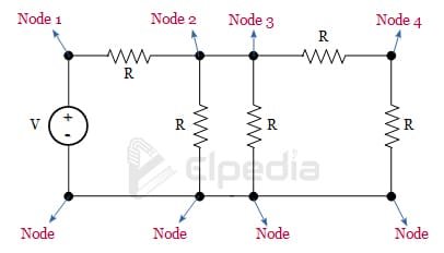
In the given circuit, there is no element between the adjacent nodes, ‘Node 2’ and ‘Node 3’, hence both can be merged into a single node.
Similarly, at the bottom side, there is no element between any of the adjacent nodes and hence all the bottom nodes can be merged into a single node.
Branch
The circuit elements like sources, resistor, inductor, capacitor, etc., that is connected in between two nodes constitute a branch. A branch may have one or more components connected in series.
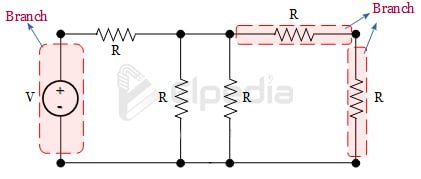
In the above circuit, the branches are shown. As you can observe, the circuit elements or components connected between two node(black dots) is called a branch.
Loop
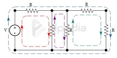
Any closed path of an electric circuit is called a loop. A loop starts from a node, may traverse through different nodes and end at the starting node without crossing any node twice.
In the below example, the different loops are shown for your reference.
Common circuit elements include the resistor (dissipates energy via electrical resistance), capacitor (stores energy in an electric field), inductor (stores energy in a magnetic field), voltage source, current source, switch, circuit breaker, fuse, and semiconductor devices like diodes and transistors.
Core Classification of Electrical Networks
Electrical networks can be classified based on different characteristics of their elements and behavior. Each classification focuses on a specific property of the network. The main classification pairs are:
- Linear vs Nonlinear – whether V–I relationships are proportional.
- Active vs Passive – whether elements supply or only consume energy.
- Bilateral vs Unilateral – whether behavior is direction-independent.
- Lumped vs Distributed – whether parameters are localized or spread spatially.
- Time-Invariant vs Time-Varying – whether component values change with time.
- Static vs Dynamic – whether the network stores energy and has memory.
- Reciprocal vs Non-Reciprocal – whether transfer behavior between ports is symmetric.
- AC vs DC – whether current alternates or remains direct current.
- Series vs Parallel – how elements are connected structurally.
- Balanced vs Unbalanced – equality of phase magnitudes in multi-phase systems.
- Symmetrical vs Unsymmetrical – geometrical or parameter symmetry.
A real-world electrical network can belong to several categories at the same time, depending on its characteristics.
For example, a household AC lighting circuit is generally linear, passive, bilateral, time-invariant, AC, and connected in parallel. Other types of networks, such as resistive, RLC, polyphase, and protection networks, are discussed separately in later sections.
Linear and Nonlinear Electrical Networks
A linear network is an electrical network in which the relationship between voltage and current is linear. The circuit parameters remain constant, and the response of the network is directly proportional to the applied input.
Ideal resistors obeying Ohm’s law, capacitors, and inductors are the other examples of linear elements under appropriate operating conditions.
A key property of a linear network is the principle of superposition, which states that the total response produced by multiple independent sources is equal to the algebraic sum of the responses produced by each source acting individually.
A nonlinear network is an electrical network that contains at least one nonlinear element whose voltage–current relationship is not proportional or does not follow a straight-line characteristic. The V–I characteristic of such an element is generally curved and changes with the applied voltage or current.
Diodes, transistors, and magnetic cores operating in saturation are the common examples of non linear components.
In a nonlinear network, the principle of superposition does not apply, and the network may exhibit different operating points depending on the applied conditions.
- Linear examples: A DC resistor network, a small-signal audio amplifier, and a transmission line with constant distributed RLC parameters are examples of linear networks, provided their components operate within their linear operating regions.
- Nonlinear examples: A diode rectifier circuit, a transistor-based switching circuit, and saturable reactors used in power systems are examples of nonlinear networks because their voltage–current characteristics change with the applied voltage or current.
Linear networks can be solved with Kirchhoff’s laws, Thévenin’s and Norton’s theorems, and phasor methods. Nonlinear networks often require iterative or numerical methods such as SPICE simulation or piecewise-linear approximations.
Active and Passive Networks
An active network is an electrical network that contains at least one active element capable of supplying electrical energy or providing power gain.
Voltage sources, current sources, generators, transistors, and operational amplifiers are common examples of active elements. An active network can deliver net energy to another circuit or amplify an electrical signal.
A passive network is an electrical network composed only of passive elements that dissipate, store, or transfer energy, without generating net energy or providing power gain.
Resistors, capacitors, inductors, ideal transformers, and transmission lines are common examples of passive elements. A passive network cannot deliver more energy than it receives; some of the input energy may be stored temporarily or dissipated as losses.
- Active example: An inverter-based solar PV system with control electronics and a motor drive circuit using IGBTs are active networks because they contain energy sources and active switching or control devices.
- Passive example: An RLC filter connected between a source and a load and a distribution transformer with cables supplying a residential area are passive networks.
Active networks are widely used in power conversion, amplification, control, and signal processing, whereas passive networks are commonly used for filtering, impedance matching, energy storage, and power distribution.
Bilateral and Unilateral Networks
A bilateral network is an electrical network that behaves in the same manner regardless of the direction of current or voltage between its terminals. In other words, reversing the direction of current does not change the electrical characteristics of the network.
Resistors, ideal inductors, capacitors, and symmetrical transmission lines are common examples of bilateral elements.
A unilateral network is an electrical network whose behavior depends on the direction of current or voltage. Its electrical characteristics are different when the direction of current or signal is reversed.
Rectifier diodes, controlled rectifiers, and transistors in certain configurations are examples of unilateral elements because they allow or control current predominantly in one direction.
- Bilateral Example: AC power distribution networks can be considered bilateral when their circuit elements exhibit the same electrical characteristics regardless of the direction of current flow. The direction of power flow may change depending on the operating conditions, but the network characteristics remain essentially the same.
- Unilateral Example: A rectifier circuit at the input of a computer system is an example of a unilateral network because its diodes allow current to flow predominantly in one direction. LED driver circuits can also exhibit unilateral behavior when their semiconductor devices restrict current flow to a particular direction.
Bilateral networks can generally be analyzed using standard circuit theorems such as the superposition, Thevenin, and Norton theorems.
Unilateral networks are widely used in rectification, switching, protection, and signal-processing applications, where directional behavior is essential.
Lumped and Distributed Networks
This classification depends on how elements are modeled relative to signal wavelength.
A lumped network is an electrical network in which the circuit parameters such as resistance, inductance, capacitance, and conductance are assumed to be concentrated at discrete components or points.
The propagation time of the electrical signal through the network is considered negligible, so voltage and current can be analyzed primarily as functions of time.
Most low-frequency electrical circuits, such as 50/60 Hz power circuits, DC power supplies, and conventional control circuits, can be accurately modeled as lumped networks.
As a general rule, a network can be treated as lumped when its physical dimensions are much smaller than the signal wavelength, typically less than one-tenth of the wavelength (λ/10).
A distributed network is an electrical network in which the circuit parameters are distributed continuously along the length of the network. In this type of network, voltage and current vary with both time and position, so signal propagation, transmission-line effects, and reflections must be considered.
At 60 Hz, the wavelength of an electromagnetic wave is approximately 5,000 km, so many conventional power circuits can be approximated using lumped models.
However, at higher frequencies, such as radio-frequency (RF) applications, the wavelength becomes much shorter, making distributed models necessary.
- Lumped Example: household wiring feeding a single room circuit breaker panel, motor starter circuits, small PCB based analog circuits.
- Distributed Example: long power transmission lines between cities, high-speed communication cables, RF coaxial lines.
In simple terms, a lumped network treats circuit parameters as concentrated at specific points, whereas a distributed network considers them to be spread continuously throughout the network.
Time-Invariant vs Time-Varying Networks
This classification is based on whether the parameters of the network change with time.
A time-invariant network is an electrical network in which the values of its circuit parameters, such as resistance, inductance, capacitance, and source values, remain constant with time. Therefore, the network exhibits the same response to the same input, regardless of when the input is applied.
A time-varying network is an electrical network in which at least one circuit parameter changes with time. As a result, the behavior of the network can change even when the applied input remains the same.
- Time-invariant Examples : A circuit consisting of fixed resistors, inductors, and capacitors is generally considered a time-invariant network, provided their parameters remain constant during operation.
- Time-varying Examples : Switched-capacitor circuits, pulse-width-modulated (PWM) converters, and systems whose parameters are continuously adjusted by control circuits.
Time-invariant systems are often analyzed with steady-state or phasor methods. Time-varying require differential equations, transient analysis, and simulation tools like SPICE or EMT-type solvers.
Static vs Dynamic Networks
This classification is based on whether the network contains energy-storage elements and whether its output depends on the past behavior of the circuit.
A static network is an electrical network that does not contain energy-storage elements such as capacitors or inductors. Its output at any instant depends only on the instantaneous input. Networks consisting primarily of resistive elements and independent sources are examples of static networks.
A dynamic network is an electrical network that contains energy-storage elements, such as capacitors and inductors. Its voltage and current depend not only on the present input but also on the initial conditions and previous behavior of the circuit.
- Static Examples : A simple DC resistive network in a lamp dimmer at fixed setting.
- Dynamic Examples : An RLC filter in a 50 Hz power factor correction circuit, a switched-mode power supply network where duty cycle changes over milliseconds; smart grid devices that continuously adjust tap changers and capacitor banks.
In simple terms, a time-invariant or time-varying network is classified according to whether its parameters change with time, whereas a static or dynamic network is classified according to whether its behavior involves energy storage and dependence on past conditions.
Reciprocal and Non-Reciprocal Networks
A reciprocal network is a network in which the transfer response remains the same when the positions of the source and load are interchanged, provided that the same operating and loading conditions are maintained.
Networks composed of resistors, inductors, capacitors, and ideal transformers, without active components, are generally reciprocal. In power systems, most passive transmission lines and cables are generally treated as reciprocal networks.
For such networks, the relevant network parameter matrices exhibit symmetry, which is a mathematical representation of reciprocity.
A non-reciprocal network is a network whose transmission characteristics depend on the direction of signal or power flow. The response from port 1 to port 2 is therefore different from the response from port 2 to port 1.
Examples include transistor amplifiers, which can provide gain primarily in one direction, and RF circulators and isolators, which are specifically designed to control the direction of signal transmission.
Some power-electronic converters can also exhibit non-reciprocal behavior because of their switching and control mechanisms. It is predominantly used in communication and measurement systems.
The concept of reciprocity simplifies network analysis and testing. For a reciprocal network, the source and response ports can be interchanged without changing the transfer relationship under the same conditions. This allows engineers to use equivalent test configurations and reduces the number of measurements required to characterize a network.
AC and DC Networks
A DC network carries direct current where voltages remain constant or slowly varying. Typical sources include a battery, DC power supplies, and rectified outputs from AC mains.
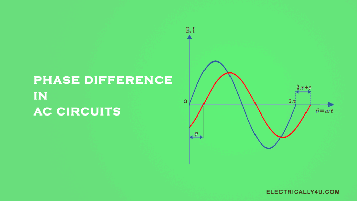
An AC network carries alternating current where voltages and currents change polarity periodically – often sinusoidal at 50 Hz or 60 Hz for power systems. Frequency, phase, and amplitude are key quantities. Impedance combines resistance, inductive reactance, and capacitive reactance.
DC network examples: Automotive 12 V and 48 V systems, DC buses in solar PV arrays, battery backup systems in data centers that also host enterprise private network infrastructure for computers.
AC network examples: Residential and industrial three-phase systems, the national power grid, AC distribution in campuses and metropolitan areas (sometimes compared loosely to a metropolitan area network in computing, but carrying electrical power instead of data).
DC networks are analyzed with Ohm’s law and Kirchhoff’s laws. AC networks use phasor representation, complex impedance, power factor, and concepts like real power, reactive power (measured in VARs), and apparent power.
Series, Parallel, Balanced, and Symmetrical Networks
These structural classifications describe how elements are connected and whether the network exhibits symmetry.
In a series network, elements are connected end-to-end so the same current flows through each. Total resistance is Rtotal = R₁ + R₂ + … and total voltage is the sum of individual drops. If one element fails open, current ceases in the entire path. Example: a series R–L–C filter or a series arc-fault detection circuit in a breaker.
In a parallel network, elements share the same pair of nodes. Each branch gets the same voltage; currents split among branches. Total resistance is always less than the smallest individual branch resistance (1/Rtotal = 1/R₁ + 1/R₂ + …).
Household distribution connects each appliance in parallel across phase and neutral, adding redundancy – one branch failing doesn’t kill others.
A balanced network (especially in three-phase AC) has all phase impedances equal in magnitude and symmetrically displaced by 120°. Line-to-line voltage equals √3 times phase voltage.
An unbalanced network has unequal impedances or loads, leading to neutral currents, unequal phase voltages, and increased losses.
A symmetrical network has physical and electrical properties that repeat in a symmetric pattern – equidistant conductors in a three-phase line, or a lattice network with mirror symmetry.
An unsymmetrical network has uneven conductor spacings or unequal line parameters, which is common in practical distribution systems.
Series vs parallel affects reliability and voltage/current distribution. Balanced symmetrical networks simplify calculations and minimize losses. Unbalanced and unsymmetrical networks may require sequence component analysis (positive, negative, zero sequences).
Other Important Network Types in Electrical Engineering
Beyond the main classification pairs, several specialized network types appear frequently.
Resistive networks contain only resistors and sources. They appear in measurement bridges (Wheatstone bridge) and load banks. RL, RC, LC, and RLC networks combine resistors with inductors and capacitors for filters, oscillators, snubber circuits, and power factor correction.
Polyphase and three-phase networks carry multiple phase-shifted AC waveforms and dominate power transmission and heavy industry. Star (Y) and delta (Δ) connections are the two main structural patterns. Star–delta and delta–star transformations simplify complex impedance networks into equivalent forms for easier analysis.
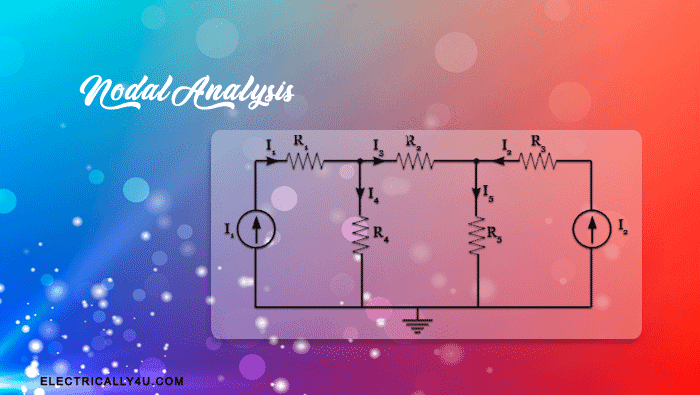
Mesh and node-based network views treat networks as combinations of independent loops (meshes) and nodes, supporting mesh-current and nodal-voltage analysis methods.
Electronic filter and amplifier networks use active devices like op-amps in ladder or feedback configurations to control gain, frequency response, and stability.
Protection and control networks include relays, instrument transformer networks, and breaker trip circuits that detect faults – a short circuit creates a low resistance path where current exceeds safe levels – and operate the circuit breaker to isolate faulty sections.
Relationship Between Electrical Networks and Computer Networks
While this article focuses on electrical networks, it helps to clarify how they differ from – and coexist with – computer networks.
Computer networks serve to connect computers and devices to exchange data. They are built physically on top of electrical networks.
Network switches, routers, servers, and wi fi access points all contain complex electrical networks – power supplies, signal-conditioning circuits, high-speed data links.
A university campus area network depends on an underlying electrical distribution network supplying AC via transformers, switchgear, and cable circuits analyzed using the electrical network types described in this article (AC, three-phase, balanced, predominantly linear and passive).
Both fields share terminology – “network nodes,” “load,” “distribution” – but refer to different physical quantities. In electrical networks, the concern is electric current and voltage. In computer networks, the concern is data packets and protocols. Understanding the distinction prevents confusion when studying either discipline.