Electrical Engineering Symbols – A Complete Guide for Electrical and Electronics Engineers
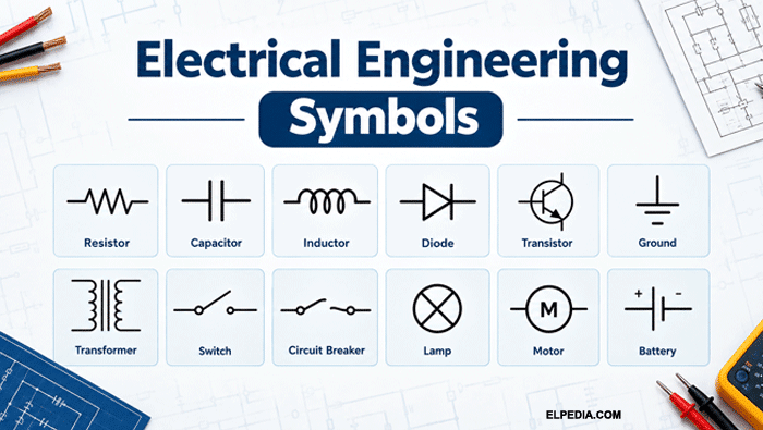
Electrical symbols are standardized graphic icons that represent electrical components, electronic devices, and functions in circuit diagrams, wiring plans, and control schematics. Rather than drawing a realistic picture of every part, electrical and electronics engineers rely on these simplified representations to communicate designs quickly and unambiguously.
Electrical engineering schematics use standardized symbols to represent components, and this matters because symbols simplify complex circuit designs. They provide a universal language for electrical professionals, reducing errors in circuit analysis and speeding up design review.
Whether you are an experienced engineer, a technician wiring an industrial panel, or a student interpreting electrical schematics for the first time, understanding these graphical symbols is a foundational skill.
Most modern electrical and electronic symbols follow national and international standards set by bodies like the International Electrotechnical Commission (IEC 60617) and the IEEE.
Electrical symbols are intentionally designed as abstractions of real-world components. For example, a physical switch may look completely different from its schematic symbol, while a real diode bears little resemblance to the simple diode symbol used in a circuit diagram. This abstraction is important because it removes unnecessary physical details and focuses on the component’s electrical function.
This article presents a large, categorized collection of electrical engineering symbols covering power supply symbols, circuit symbols, semiconductor devices, protection, machines, logic gates, communication, and more.
Standards, Conventions, and Reading Electrical Symbol Diagrams
Understanding the standards behind electrical symbols helps you interpret any diagram regardless of where it was drawn. IEC 60617 is a key reference for graphical symbols, containing approximately 1,900 standardized entries.
The IEC provides globally aligned schematic symbols for electrical devices, while the IEEE publishes North American standards for electrical symbols. Symbols can vary slightly between standards like IEC and ANSI/IEEE – for example, the resistor symbol is a zigzag line in ANSI but a rectangular box in IEC.
Key visual conventions to know:
- Solid lines represent active conductors; a dotted or dashed line indicates mechanical linkage, shielding, or optional connections.
- Arrows indicate current flow, signal direction, or variable elements.
- Polarity marks (+/−, K/A) and reference designators (R1, C3, Q5) label symbols with ratings and reference designators for clarity.
- A dot at a wire intersection means an electrical connection (junction); no dot means wires simply cross without contact.
Use standard symbols to avoid confusion and errors. Follow industry standards like IEEE and IEC for consistency, and use CAD tools with built-in symbol libraries for accuracy. Ensure symbols are clear and easily readable in diagrams.
Consider a simple circuit: a DC battery connects through a switch to a lamp, which returns to the battery negative terminal. When the switch closes, current flow goes from battery positive, through the switch, through the lamp (which lights), and back. This basic reading skill scales to interpreting electrical diagrams of any complexity.
Basic Electrical Symbols
These are the most frequently used circuit symbols representing fundamental concepts like connections, conductors, and grounding. Common electrical symbols include lines for wires and zigzags for resistors.
A junction is indicated by a dot where wires connect in a schematic. Understanding these basic schematic symbols is essential before interpreting more complex electronic circuits.
Name | Symbol | Description |
|---|---|---|
Ground / Earth (GND) |  | The shorthand for ground is GND; represents the reference point or earth connection in a circuit. |
Protective Earth | 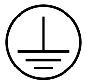 | Safety grounding connection for enclosures and chassis to protect components and people. |
Chassis Ground | 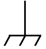 | Connects to the metal chassis of a device rather than true earth. |
Electrical Conductor | 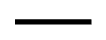 | Represents a wire carrying an electrical signal or power between components. |
Line Junction (Node) | 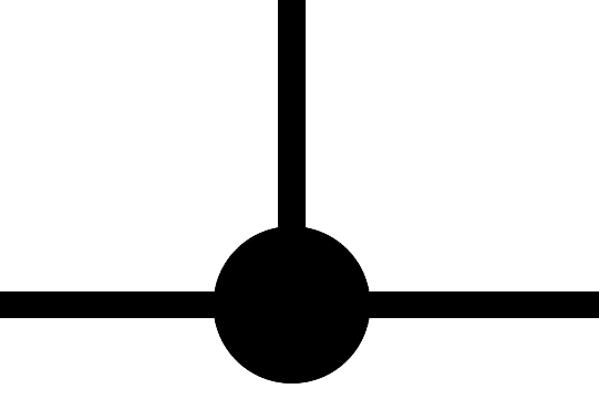 | Indicates wires are electrically connected at that point. |
Line Crossing (No Connection) | 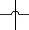 | Wires cross but share no electrical connection. |
Terminal | 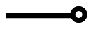 | A connection point where an external wire or component attaches. |
Bus Bar |  | Heavy conductor distributing power to multiple connected branches. |
Neutral Conductor (N) |  | Reference conductor in AC power supply systems, typically at zero potential. |
Phase Conductor (L) |  | Carries AC line voltage; three-phase systems use L1, L2, L3 designations. |
Lamp / Indicator | 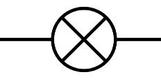 | Represents a lamp or indicator light used as a generic load. |
Fuse | 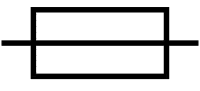 | A fuse symbol indicates a safety device that melts under excess current to protect components. |
Electrical Circuit Symbols: Sources, Sinks, and Switches
This category covers core power supply symbols and switching/control elements that appear in virtually every circuit.
Name | Symbol | Description |
|---|---|---|
Single-Cell Battery | 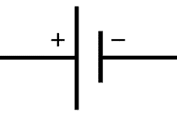 | Represents a single electrochemical cell providing DC voltage. |
Multi-Cell Battery | 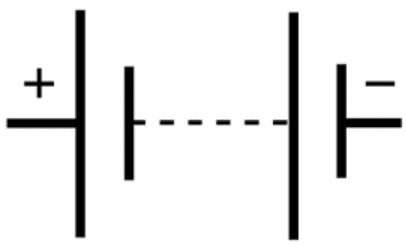 | A battery symbol represents multiple cells connected together; a DC voltage source is represented by alternating long and short parallel lines. |
AC Voltage Source | 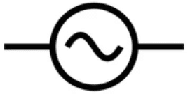 | An AC voltage source is shown as a circle containing a sine wave; used in power supply symbols for mains or signal sources. |
DC Voltage Source | 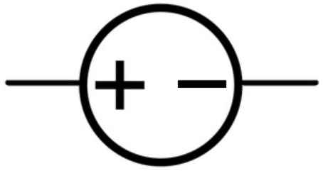 | Provides constant-polarity voltage; sometimes shown as battery style. |
Current Source | 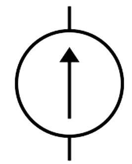 | Supplies constant current regardless of voltage levels across its terminals. |
Controlled Source | 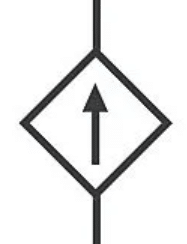 | Voltage or current output controlled by another electrical signal in the circuit. |
Resistor (Load) | 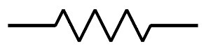 | The resistor symbol is a zigzag line or a rectangular box; dissipates energy as heat. |
Heating Element | 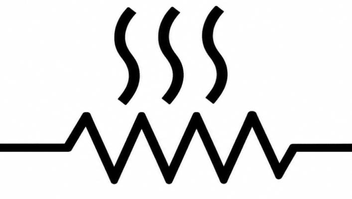 | Resistive element specifically designed for thermal output. |
Generic Motor Load | 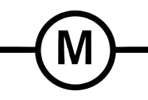 | Represents any motor connected as a load in schematic diagrams. |
SPST Switch | 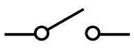 | A single pole single throw switch is illustrated as a break in a line with a lever; simplest on/off control. |
SPDT Switch | 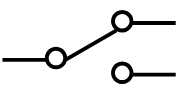 | A single pole double throw switch routes one input to either of two outputs. |
DPST Switch | 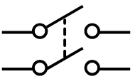 | A double pole switch controlling two separate circuits simultaneously. |
DPDT Switch | 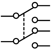 | A double pole double throw switch; routes two inputs each to one of two outputs. |
Open Pushbutton Switch (NO) | 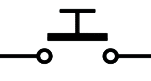 | An open pushbutton switch closes momentarily when pressed, then returns to open state. |
Pushbutton NC | 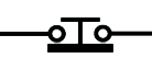 | Normally closed momentary switch that opens when pressed. |
Selector Switch | 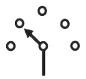 | Allows selection among multiple circuit paths. |
Emergency Stop | 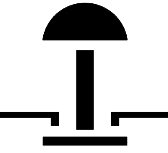 | Latching safety device for immediate circuit disconnection. |
Semiconductor and Electronic Component Symbols
Semiconductor and electronic symbols represent active devices used by electronics engineers for signal processing, amplification, and switching in electronic circuits.
Name | Symbol | Description |
|---|---|---|
PN Diode | 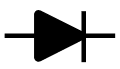 | A diode symbol allows current to flow in only one direction; the triangle indicates the anode. |
Zener Diode | 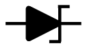 | Allows reverse breakdown at a defined voltage; used for voltage regulation. |
Schottky Diode | 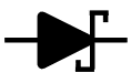 | Lower forward voltage drop than standard diodes; common in high-speed switching. |
LED | 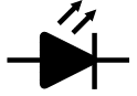 | Light-emitting diode; arrows represent emitted light from the junction. |
Photodiode | 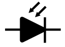 | Generates current when exposed to light; arrows point toward the device. |
Varactor Diode | 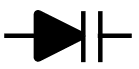 | A variable capacitor controlled by reverse bias voltage. |
Bridge Rectifier | 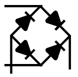 | Converts AC to DC using four diodes in a bridge configuration. |
NPN BJT | 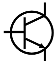 | A bipolar junction transistor; the transistor symbol shows three terminals: base, collector, and emitter. Arrow points outward for NPN. |
PNP BJT | 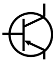 | Complementary to NPN; arrow on emitter points inward toward the base. |
N-Channel JFET | 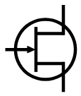 | Field-effect transistor controlled by gate voltage; arrow indicates n-channel. |
N-Channel Enhancement MOSFET | 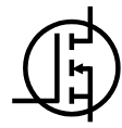 | Normally off; conducts when gate voltage exceeds threshold; among key transistor symbols. |
IGBT | 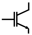 | Insulated-gate bipolar transistor; handles high power with MOS input simplicity. |
Thyristor / SCR |  | Latching device that conducts once gate-triggered; used in power control. |
TRIAC | 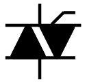 | Controls AC current flow in both directions; common in dimmers. |
Fixed Capacitor |  | A capacitor is represented by two parallel lines or plates; stores electric charge. |
Polarized Capacitor | 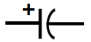 | Electrolytic type; must observe correct polarity to avoid damage. |
Variable Capacitor |  | Adjustable capacitance; a variable capacitor is used in tuning circuits. |
Inductor | 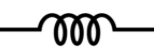 | An inductor is depicted as a series of loops or coils; stores energy in a magnetic field. |
Variable Inductor | 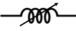 | The inductor symbol with an arrow represents adjustable inductance. |
Ferrite Bead | 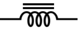 | Suppresses high-frequency noise on signal lines. |
Crystal Resonator |  | Provides precise frequency reference for oscillator circuits in electronic devices. |
Potentiometer | 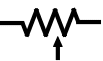 | Three-terminal variable resistor used for adjustable voltage levels. |
Op-Amp | 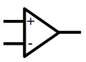 | An operational amplifier symbol is a triangle with two inputs and one output; fundamental analog building block. |
Optocoupler | 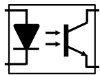 | Provides galvanic isolation between input and output using light coupling. |
Generic IC | 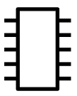 | Represents an integrated circuit package; pin labels identify function of each connection. |
Measuring Instrument and Indicator Symbols
Measurement instruments like ammeter, voltmeter, and ohmmeter have specific symbols that appear in test circuits, power systems, and control panels to show where quantities are monitored.
Name | Symbol | Description |
|---|---|---|
Voltmeter |  | Measures voltage across two points; connected in parallel. |
Ammeter |  | Measures current through a conductor; connected in series. |
Wattmeter |  | Measures real power consumed by a load. |
Frequency Meter |  | Monitors the frequency of an AC electrical signal. |
Energy Meter |  | Records cumulative energy consumption over time. |
Oscilloscope |  | Displays voltage waveforms versus time for analysis. |
Pilot Lamp | 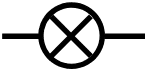 | Panel-mounted indicator showing circuit status (on/off). |
7-Segment Display | 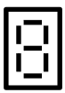 | Digital numeric indicator used in instrument panels. |
Current Transformer (CT) | 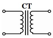 | Enables safe current measurement in high-voltage systems by stepping down current. |
Voltage Transformer (VT) | 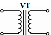 | Steps down high voltage for safe measurement by instruments. |
Electrical Protection and Safety Symbols
Protection symbols show devices that detect faults and disconnect or limit currents and voltages. Standards for electrical symbols help ensure clarity and safety, and these symbols are crucial in one-line diagrams for compliance.
Name | Symbol | Description |
|---|---|---|
Cartridge Fuse | | Melts under excess current; protects downstream components. |
MCB | 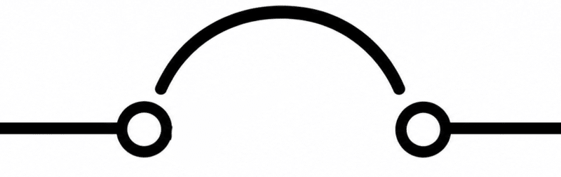 | Miniature circuit breaker; resets manually after tripping. |
MCCB | 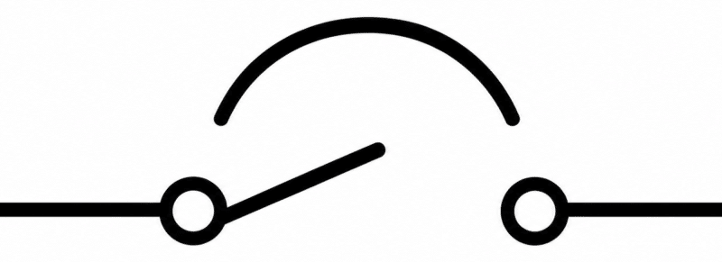 | Molded case circuit breaker for higher-rated circuits. |
RCD / RCCB | 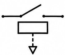 | Detects earth leakage current to protect against electric shock. |
Surge Arrester | 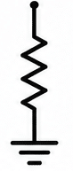 | Diverts transient overvoltages safely to earth. |
Relay Coil | 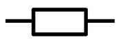 | The relay symbol represents an electromagnetic coil that actuates switching contacts. |
Relay NO Contact | 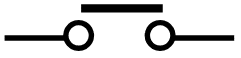 | Normally open; closes when the relay coil energizes. |
Relay NC Contact | 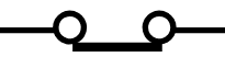 | Normally closed; opens when the relay coil energizes. |
Thermal Overload Relay | 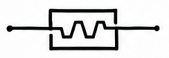 | Protects motors from sustained overcurrent by tripping on heat. |
Time-Delay Relay | 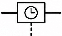 | Introduces on-delay or off-delay before contact operation. |
Contactor | 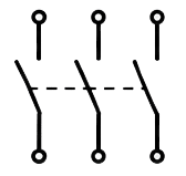 | High-current switching device for motor and power circuits. |
Electric Shock Hazard | 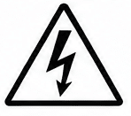 | Warning pictogram indicating danger of electrocution. |
Electrical Machine and Power System Symbols
These symbols represent rotating machines, transformers, and high-level power system elements. The transformer symbol represents two coils linked by an iron core, and appears across generation, transmission, and distribution diagrams.
Name | Symbol | Description |
|---|---|---|
DC Motor | 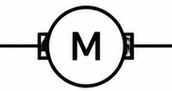 | Converts DC electrical energy into mechanical rotation. |
DC Generator | 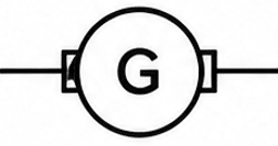 | Converts mechanical energy into DC electrical output. |
Three-Phase Induction Motor | 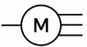 | Most common industrial motor; runs on three-phase AC power supply. |
Synchronous Generator | 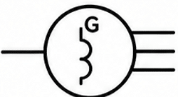 | Alternator producing AC at synchronous speed; core of power generation. |
Stepper Motor | 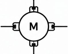 | Rotates in discrete steps; used in precision positioning. |
Single-Phase Transformer | 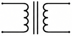 | Transfers AC energy between circuits via a magnetic field in the core. |
Three-Phase Transformer | 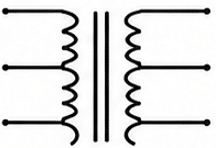 | Used in power transmission and distribution for voltage conversion. |
Autotransformer | 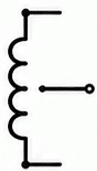 | Shares a common winding between primary and secondary; compact design. |
Transmission Line | 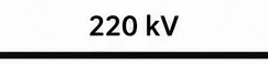 | Carries bulk power over long distances at high voltage. |
Bus Bar (Power System) | 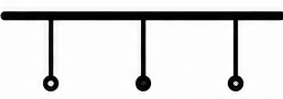 | Central conductor in substations connecting multiple circuit elements. |
Circuit Breaker (One-Line) | 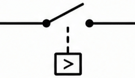 | Isolates faulted sections; shown on single-line diagrams in substations. |
Isolator / Disconnector | 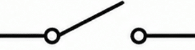 | Provides visible isolation for maintenance; no load-breaking capability. |
Capacitor Bank | 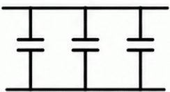 | Provides reactive power compensation and power factor correction. |
Electrical Wiring and Installation Symbols
These wiring symbols appear in building electrical plans and installation drawings rather than detailed electronic schematics.
Name | Symbol | Description |
|---|---|---|
Single Socket Outlet | 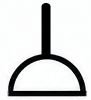 | Standard power outlet for single plug connection. |
Double Socket Outlet | 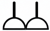 | Accommodates two plugs at one location. |
Ceiling Light Point | 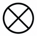 | Indicates position of overhead luminaire. |
Fluorescent Fixture | 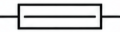 | Represents linear fluorescent or LED tube fixture. |
Emergency Light | 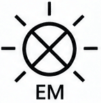 | Battery-backed luminaire for emergency egress. |
Wall Switch | 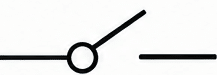 | Controls lighting or other components from wall position. |
Two-Way Switch | 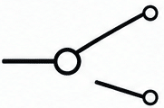 | Allows control from two locations (called 3-way in US terminology). |
Junction Box | 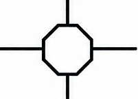 | Enclosure where wires are spliced or routed at T junctions. |
Conduit | 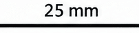 | Protective tube routing wires through buildings. |
Main Earthing Terminal | 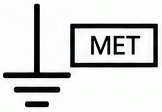 | Central bonding point for building’s protective earthing system. |
Thermostat | 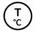 | Controls heating or cooling equipment based on set temperature. |
Doorbell Push Button | 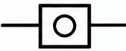 | Momentary contact to activate bell or chime circuit. |
Digital Logic and Binary Circuit Symbols
Digital circuit symbols represent logic gates and storage elements used in computer and control electronics. Standardized symbols enhance communication among engineers working on digital design.
Name | Symbol | Description |
|---|---|---|
AND Gate | 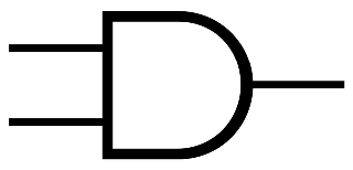 | Output is high only when all inputs are high. |
OR Gate | 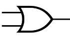 | Output is high when any input is high. |
NOT Gate (Inverter) | 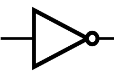 | Inverts the input signal; a single-input logic element. |
NAND Gate | 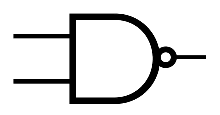 | Output is low only when all two inputs (or more) are high. |
NOR Gate | 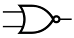 | Output is high only when all inputs are low. |
XOR Gate | 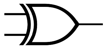 | Output is high when inputs differ; exclusive-OR function. |
XNOR Gate | 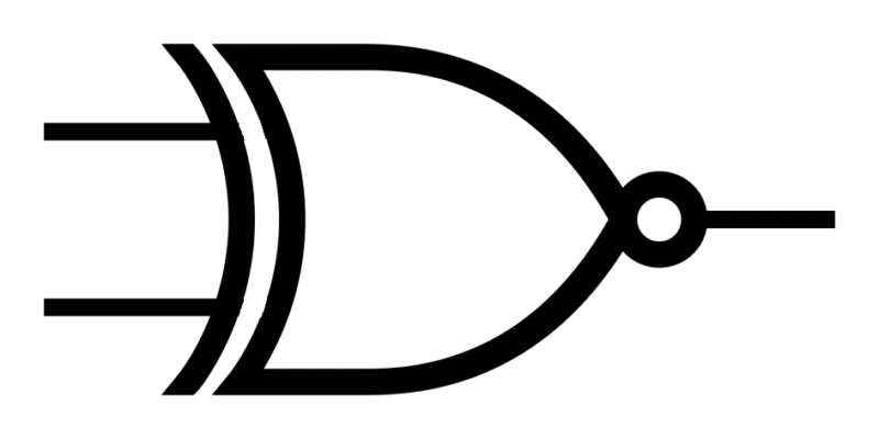 | Output is high when inputs match. |
D Flip-Flop | 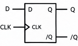 | Captures input D on clock edge; fundamental sequential storage element. A flip flop stores one bit. |
JK Flip-Flop | 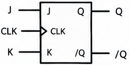 | Versatile sequential element; toggles on simultaneous J and K high. |
Multiplexer (MUX) | 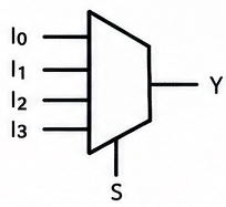 | Routes one of several inputs to a single output based on select lines. |
Decoder | 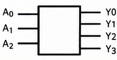 | Activates one specific output line based on binary input code. |
Schmitt Trigger Input | 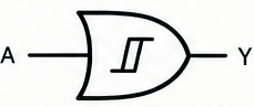 | Provides noise immunity with defined switching voltage levels. |
Communication, Control, and Miscellaneous Symbols
This group covers communication interfaces, sensors, actuators, and other components not included in earlier sections.
Name | Symbol | Description |
|---|---|---|
Antenna | 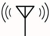 | Transmits or receives RF signals; common in wireless circuit diagrams. |
Coaxial Connector | 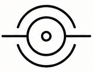 | Shielded connector for RF signal transmission. |
Optical Fiber Link | 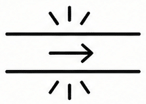 | Represents fiber-optic data connection between devices. |
Thermistor (NTC/PTC) | 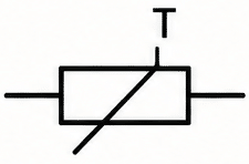 | Resistance changes with temperature; used for sensing or protection. |
LDR | 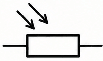 | Light-dependent resistor; resistance decreases with light exposure. |
Microphone | 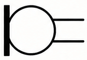 | Converts sound waves into an electrical signal for processing. |
Loudspeaker | 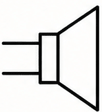 | Converts electrical signal into audible sound output. |
Solenoid | 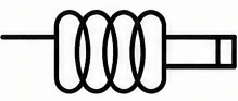 | Electromagnetic actuator producing linear motion when energized. |
Buzzer / Alarm | 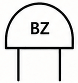 | Audible alert device activated by circuit signal. |
Proximity Sensor | 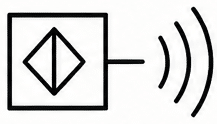 | Detects nearby objects without physical contact; used in automation. |
AGS devices and similar curated symbol collections offer ready-made component libraries that can be loaded directly into CAD software, saving engineers from drawing each symbol manually.
Mastering these broad categories of electrical symbols helps electrical and electronics engineers design, document, and troubleshoot complex systems efficiently. Electrical symbols are standardized to reduce confusion and errors, and using symbols reduces errors in circuit analysis while supporting industry compliance with safety standards.
Symbols provide a universal language – from the simplest switch symbol to complex schematic diagrams of power systems – that keeps every professional on the same page.
Bookmark this guide as your go-to reference. Whenever you encounter an unfamiliar symbol in electrical schematics or circuit diagrams, return here to identify it quickly and avoid confusion on your next project.