Parallel Operation of Single phase Transformer
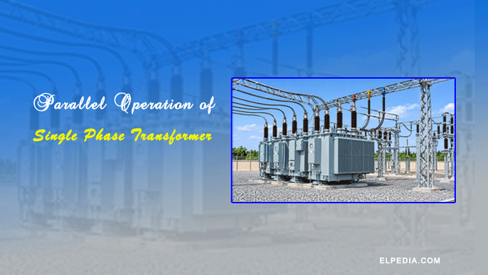
Parallel operation of transformers refers to the process of connecting two or more transformers such that their primary windings are connected to a common supply, while their secondary windings are connected to a common load bus.
In the case of single-phase transformers, both transformers receive the same single-phase supply voltage and deliver electrical power to a common load. They share the total load current and apparent power while maintaining the required secondary voltage.
Parallel operation is widely used in electrical power distribution systems t0 increase load-handling capacity, improve reliability, and provide operational flexibility.
Understanding the parallel operation of single phase transformers provides a foundation for studying the parallel operation of three-phase transformers, which involves additional considerations such as phase sequence and phase displacement.
This article explains the necessity of parallel operation, the essential conditions for connecting transformers in parallel, load-sharing equations for equal and unequal voltage ratios, and an introduction to the parallel operation of three-phase transformers.
Necessity of Parallel Operation of Transformers
Parallel operation of transformers is commonly used when a single transformer cannot meet the required load demand or when greater reliability and operational flexibility are needed. The main reasons for operating transformers in parallel are explained below.
Basic Concept and Phasor Representation of Parallel Operation
Consider two single-phase transformers, T1 and T2, with their primary windings connected to a common supply (for example, 11 kV) and their secondary windings connected to a common load bus (for example, 230 V). This arrangement allows both transformers to supply power to the same load.
When identical transformers with equal voltage ratios are connected in parallel, their secondary voltages have the same magnitude and phase angle. Therefore, no circulating current flows between them under no-load conditions.
When a load is connected, the total load current is shared between the two transformers according to their respective equivalent impedances, which consist of resistance and reactance ( ). The transformer with lower equivalent impedance carries a greater share of the load current.
For successful parallel operation of single phase transformers, their secondary voltage phasors must have the same magnitude and phase angle. Any difference in voltage magnitude, due to unequal transformation ratios, or phase angle results in a voltage difference between the secondary terminals. This voltage difference produces a circulating current between the transformers, even when no external load is connected.
Phasor diagrams are useful for understanding the relationship between the secondary voltages of parallel transformers. Similarly, an equivalent circuit helps explain how the load current is divided between the transformers according to their internal impedances.
Essential Conditions for Parallel Operation of Transformers
For the successful parallel operation of transformers, certain electrical conditions must be satisfied. These conditions are generally classified into two categories: essential conditions and desirable conditions.
Essential Conditions
The following conditions must be satisfied to avoid short circuits and ensure proper parallel operation.
- Same Polarity: Both transformers must have the same polarity. If transformers with opposite polarities are connected in parallel, their secondary voltages will oppose each other, resulting in a short circuit and a very high circulating current. Therefore, the polarity of both transformers must be checked before connecting them in parallel.
- Same Voltage Ratio: Both transformers should have the same voltage transformation ratio. If their voltage ratios differ, their secondary voltages will be unequal, even under no-load conditions. This difference produces circulating currents between the transformers, which may cause overheating and additional losses.
- Same Frequency Rating: Both transformers must have the same rated frequency and operate at the same supply frequency. For example, a 50 Hz transformer should not be operated in parallel with a 60 Hz transformer on the same supply system.
- Same Phase Sequence and Phase Displacement: For three-phase transformers, both units must have the same phase sequence and phase displacement. They should also have compatible winding connections and vector groups. Otherwise, a large circulating current may flow when their secondary terminals are connected together.
Desirable Conditions
The following conditions are desirable to ensure proper load sharing and efficient operation of transformers connected in parallel.
- Same Percentage Impedance: Both transformers should have the same percentage impedance, referred to a common kVA base. This ensures that the load is shared approximately in proportion to their rated capacities. A difference in impedance causes unequal load sharing, which may result in one transformer becoming overloaded before the other.
- Similar X/R Ratio: The resistance-to-reactance (X/R) ratios of both transformers should be similar. This helps the transformers share both active power (kW) and reactive power (kVAR) proportionally, maintaining similar operating power factors.
- Compatible kVA Ratings: Transformers with identical kVA ratings are preferred for parallel operation. However, transformers with different kVA ratings can also operate in parallel, provided their percentage impedances are suitably matched so that the load is shared according to their respective ratings.
- Same Tap Changer Position: The tap changer positions of both transformers should be adjusted to obtain nearly equal secondary voltages. This minimises circulating currents and ensures proper load sharing during operation.
Failure to satisfy the essential conditions may result in short circuits or excessive circulating currents. Differences in impedance, X/R ratio, and tap settings can lead to unequal load sharing, overheating, increased losses, and possible damage to the transformers.
Circulating Currents in Parallel Operation of Transformers
When two transformers having slightly different secondary voltages are connected in parallel, a circulating current flows between them, even when no external load is connected. This happens because of the voltage difference between their secondary windings.
The circulating current flows from the transformer with the higher secondary voltage to the transformer with the lower secondary voltage.
Since this current does not supply any useful load, it increases copper losses and causes additional heating in the transformer windings.
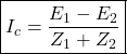
The circulating current Ic can be calculated using the following formula:
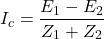
Where  and
 are no-load secondary induced EMFs of transformers 1 and 2, respectively and
 and
 are the equivalent impedances of transformers 1 and 2 referred to the secondary side (Ω), respectively.
The magnitude and phase angle of the circulating current depend on the voltage difference and the equivalent impedances of the two transformers.
If their impedance angles or X/R ratios differ, the circulating current may have different active and reactive components, affecting the power sharing and power factor of each transformer.
Numerical Example:
Consider two transformers T1 and T2 connected in parallel with the no-load secondary voltages of 230 V and 233 V, respectively.
The voltage difference between the two transformers is:

Assume that both transformers have 5% impedance on the same rating base. The 3 V voltage difference is approximately 1.3% of the rated secondary voltage. This difference can produce a significant circulating current, depending on the combined equivalent impedance of the transformers.
Methods to Minimize Circulating Currents
- Maintain the same voltage transformation ratio in both transformers.
- Ensure that the tap changer positions are properly adjusted to obtain equal secondary voltages.
- Select transformers with closely matched percentage impedances and X/R ratios.
Proper matching of secondary voltages and transformer impedances minimises circulating currents, reduces additional losses, and ensures efficient parallel operation.
Load Sharing in Parallel Operation– General Approach
When two single-phase transformers are connected in parallel, the total load current is shared between them according to their equivalent impedances.
The transformer with lower impedance carries a higher share of the load current, while the transformer with higher impedance carries a lower share.
Consider two transformers, T1 and T2, connected in parallel. Their equivalent impedances are referred to the secondary side and represented as:


The total load current  is divided between the two transformers. Using the current division principle, the current carried by each transformer is given by:
Current carried by Transformer T1:

Current carried by Transformer T2:

The apparent power (kVA) shared by each transformer can be calculated as:


Where  is the common secondary terminal voltage. The apparent power is expressed in VA; divide by 1000 to obtain kVA.
Load Sharing with Equal Voltage Ratio
When two single-phase transformers having the same voltage ratio are connected in parallel, their secondary voltages are equal. Therefore, no circulating current flows between the transformers under no-load conditions.
When a load is connected, the total load current is shared between the transformers according to their percentage impedances and kVA ratings.
Using equation (1) and (2), the ratio of the currents carried by the two transformers is written as,

For the transformers to share the load in proportion to their respective kVA ratings, the following condition must be satisfied:
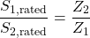
This means that the product of percentage impedance and rated kVA should be approximately equal for both transformers:

Numerical Example:
Consider two single-phase transformers connected in parallel with the following ratings: Transformer T1: 100 kVA, 5% impedance and Transformer T2: 50 kVA, 5% impedance.
Since both transformers have the same percentage impedance, they share the load current equally.
However, their rated capacities are different. Transformer T2 has only half the kVA capacity of T1. Therefore, it reaches its rated capacity earlier and may become overloaded while T1 is still operating below its rated capacity.
For proper load sharing in proportion to their kVA ratings, the percentage impedances should be inversely proportional to their rated kVA capacities.
Effect of R/X Ratio:
When the two transformers have similar resistance-to-reactance (R/X) ratios, they operate at nearly the same power factor as the load. If their R/X ratios differ significantly, the transformers may share active and reactive power unequally.
This can result in different operating power factors and increased copper losses in one of the transformers.
Load Sharing with Unequal Voltage Ratio
In the parallel operation of single phase transformers with different voltage ratios, their secondary voltage are unequal.
As a result, a circulating current flows between the transformers, even under no-load conditions. When an external load is connected, both the circulating current and the load current influence the current shared by each transformer.
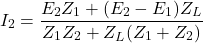
Consider two transformers, T1 and T2, having secondary induced EMFs and , and equivalent impedances and , respectively.
If a load impedance  is connected across their common secondary terminals, the currents supplied by the transformers are given by:
Current supplied by Transformer T1:
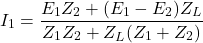
Current supplied by Transformer T2:
When no external load is connected, the load impedance approaches infinity ( ). Under this condition, the equations simplify to the circulating current condition:
Effects of Unequal Voltage Ratios
The unequal voltage ratios of transformers connected in parallel produce the following effects:
- Unequal Load Sharing: The transformer having a higher no-load secondary voltage generally supplies a greater share of the load current than its intended proportion. This results in unequal load distribution between the transformers.
- Increased Copper Losses: The circulating current flows through the transformer windings and increases copper losses. It may cause one transformer to become overloaded even when the total load is below the combined rated kVA capacity of both transformers.
- Reduced Efficiency: Additional circulating currents increase power losses, thereby reducing the overall efficiency of the parallel transformer system.
- Poor Voltage Regulation: Differences in secondary voltages and unequal load sharing can affect the voltage regulation of the parallel combination.
Numerical Illustration:
Consider two transformers connected in parallel with the following no-load secondary voltages: Transformer T1:  and Transformer T2:

Both transformers have 10% impedance on the same rating base.
The difference in their secondary voltages is:

This voltage difference produces a circulating current even when no external load is connected. Under load conditions, transformer T2, which has the higher secondary voltage, supplies a greater share of the load current.
The actual circulating current depends on the combined equivalent impedance of the transformers. Therefore, the percentage impedance alone is insufficient to calculate its exact value without knowing the transformer ratings and secondary-side voltage base.
Methods to Minimise Unequal Load Sharing
- Select transformers having the same voltage transformation ratio.
- Adjust the tap changers to obtain equal secondary voltages before connecting the transformers in parallel.
- Ensure that the percentage impedances and X/R ratios are closely matched.
- Avoid connecting transformers with significantly different secondary voltage ratings.