What is voltage? A Complete Guide to Electric Potential Difference
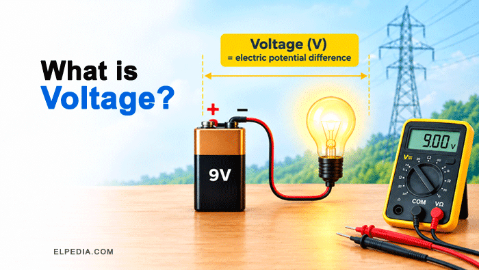
Voltage is one of the most fundamental concepts in electricity, yet it’s often misunderstood. Whether you’re a student tackling your first circuits class or a hobbyist wiring a project at home, understanding voltage is the starting point for everything else in electrical engineering.
This guide walks you through the concept step by step, from the basic definition to practical measurement, solved problems, and real-world applications.
Quick Answer: What Is Voltage?
Voltage is the electric potential difference between two points in an electrical circuit. It is the electric pressure that pushes electric charge through a conductor, and it is measured in volts (V). One volt equals one joule per coulomb of charge.
In simple terms, voltage tells us how much energy is available for each coulomb of electric charge.
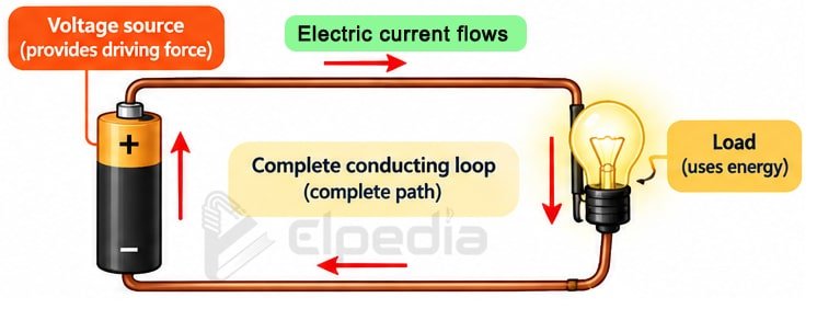
Voltage is closely related to electromotive force (EMF). EMF describes the energy supplied by an electrical source, such as a battery, per unit charge. Both voltage and EMF are measured in volts and are fundamentally related to energy per unit charge.
To make this concrete, consider a 1.5 V AA battery. Ideally, it provides 1.5 joules of energy for every coulomb of charge passing through the source. In comparison, a 230 V household supply corresponds to 230 joules per coulomb. Thus, a higher voltage represents a greater amount of energy available per unit charge.
Concept of Voltage and Electric Potential Difference
Voltage quantifies how much energy each unit of charge gains or loses as it moves between two points in an electric field. In other words, it tells us how much work is done per coulomb of charge.
It is useful to distinguish between electric potential and voltage.
- Electric potential is the potential energy per unit charge at a particular point.
- Voltage, or electric potential difference, is the difference in electric potential between two points.
This potential difference provides the driving force for charge movement when a conducting path is available.
The basic relationship between voltage (V), work (W), and charge (Q) is:
![\[\boxed{V = \frac{W}{Q}} \]](https://elpedia.com/wp-content/ql-cache/quicklatex.com-ecb0dc37d9affdf7bcc8c8c3030040d5_l3.png "Rendered by QuickLaTeX.com")
For example, if 10 J of energy is required to move 2 C of charge between two points, the potential difference is determined as,
![\[V = \frac{10}{2} = 5 \text{ V} \]](https://elpedia.com/wp-content/ql-cache/quicklatex.com-7ab9b5eb7bd390b2a46e5105e1c1cf1f_l3.png "Rendered by QuickLaTeX.com")
Voltage is a scalar quantity, meaning it has magnitude but does not have a direction like a vector. However, the polarity or sign of a voltage depends on the order in which the two points are considered.
For example, if the voltage of point B with respect to point A is defined as:
![\[V_{AB} = V_B - V_A \]](https://elpedia.com/wp-content/ql-cache/quicklatex.com-22bde9706ccb663948cec66917d6ceaf_l3.png "Rendered by QuickLaTeX.com")
then reversing the reference points gives:
![\[V_{BA} = V_A - V_B = - V_{AB} \]](https://elpedia.com/wp-content/ql-cache/quicklatex.com-1fadcd78562cbb6cb07d45d799741adf_l3.png "Rendered by QuickLaTeX.com")
This is why voltage is always specified between two points rather than as a property of an isolated point.
Key idea: Voltage represents the energy available per unit of electric charge between two points. It is a potential difference, not a property of a single point.
The unit of voltage, the volt (V), is named after Italian scientist Alessandro Volta. Around 1800, Volta developed the voltaic pile, one of the first practical sources of continuous electrical energy.
His work played an important role in the development of modern electrical science and the understanding of voltage sources.
Voltage as Energy per Unit Charge
Voltage tells you how much energy each coulomb of charge carries between two points.
For example, A 12 V car battery provides 12 joules of electrical energy per coulomb passing from its negative to its positive terminal through the circuit.
Voltage does not tell you how many charges move – that is the job of current. Even a higher voltage circuit can have tiny current if resistance is large. Therefore, voltage and current describe different aspects of an electrical circuit.
Simple problem: If a phone charger transfers 60 J of energy to 3 C of charge, what is the voltage?
![\[\text{Using the voltage equation, V} = \frac{W}{Q} \]](https://elpedia.com/wp-content/ql-cache/quicklatex.com-025ea9eab2fce315596f5b7f4811a200_l3.png "Rendered by QuickLaTeX.com")
![\[V = \frac{60}{3} = 20 \text{ V} \]](https://elpedia.com/wp-content/ql-cache/quicklatex.com-82f3602c21d1d8b3a1d7c55cb41f2ee3_l3.png "Rendered by QuickLaTeX.com")
Key idea: Voltage represents energy per unit charge, while current represents the rate at which charge flows through a circuit.
Electromotive Force (EMF) vs. Voltage
Electromotive force is the energy per unit charge supplied by a source – such as a battery or generator – when no current is drawn. In many textbooks, EMF is described as the maximum potential difference a source can provide under open-circuit conditions.
In a real electrical source, some internal resistance is always present. When current flows through the source, a portion of the voltage is lost across this internal resistance. As a result, the terminal voltage of the source becomes lower than its EMF.
For example, consider a car battery with an EMF of 12 V and an internal resistance of 0.1 Ω supplying a current of 40 A.
The internal voltage drop is:
![\[V_{\text{internal}} = I_r = 40 \times 0.1 = 4 V \]](https://elpedia.com/wp-content/ql-cache/quicklatex.com-cff2af4c62221cd721d2840c7f64e5cb_l3.png "Rendered by QuickLaTeX.com")
Therefore, the terminal voltage is:
![\[V_{\text{terminal}} = E - T_r = 12-4 = 8 V \]](https://elpedia.com/wp-content/ql-cache/quicklatex.com-2be70b53ee6b059ce669683755539a32_l3.png "Rendered by QuickLaTeX.com")
Thus, although the battery has a 12 V EMF, its terminal voltage drops to 8 V while supplying 40 A.
Both EMF and voltage are measured in volts (V) and and rely on the same energy-per-charge idea.
In summary: EMF represents the energy supplied per unit charge by an electrical source, while voltage is the potential difference between two points in a circuit. Under load, the terminal voltage of a real source can be lower than its EMF because of internal resistance.
Hydraulic Analogy: Visualizing Voltage and Current
The hydraulic analogy is one of the best ways to understand voltage, current and resistance.
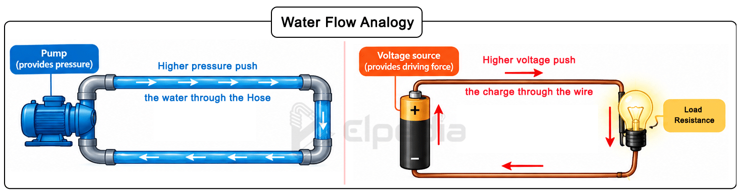
Just as higher water pressure can push more water through a hose, a higher voltage can provide a greater driving force for electric charge. However, the actual current also depends on the resistance of the circuit.
For example, imagine two water tanks connected by a pipe, as shown in the image below. If the water levels are different, water flows from the tank with higher pressure to the tank with lower pressure. If both tanks are at the same level, there is no pressure difference and, ideally, no water flows.
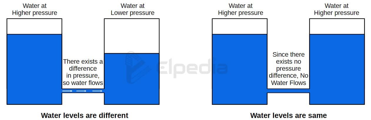
The same basic idea applies to an electrical circuit. If there is no potential difference between two points, there is no driving force for current to flow between them.
Consider a 9 V battery and a 230 V household supply. The battery can be thought of as a small source creating an electrical potential difference, while a household supply provides a much higher potential difference and can deliver substantial current under suitable conditions.
The hydraulic analogy helps visualize this difference, but it should not be taken literally: electrical shock safety depends on factors such as current, body resistance, contact conditions, and the available energy. 230 V can be extremely dangerous or fatal.
Key idea: Voltage is like the pressure difference that provides the driving force for flow, while current represents the resulting flow of electric charge and resistance opposes that flow.
Voltage vs Current: Key Differences
Voltage and current are closely related, but they represent two different quantities in an electrical circuit.
Voltage is the push that drives current through a circuit. Current is the effect – the actual flow of electric charge through a closed circuit.
Voltage provides the necessary driving force to create a steady flow of electric current, but current measures how much charge moves per second in a circuit (1 A = 1 coulomb per second).
Feature | Voltage | Current |
|---|---|---|
What it describes | Electric pressure / potential difference | Rate of charge flow |
Unit | Volt (V) | Ampere (A) |
Exists in open circuit? | Yes | No |
Measured with | Voltmeter (in parallel) | Ammeter (in series) |
Analogy | Water pressure | Water flow rate |
Danger factor | Creates the push | Delivers the shock energy |
Voltage exists even in an open circuit (like an unused wall outlet), whereas current only flows when there is a closed path.
For example, an unused battery has a potential difference between its terminals, even though no current flows when the circuit is open. Current, on the other hand, requires a complete conducting path.
The danger of an electric shock depends on several factors, particularly the current passing through the body, the duration of contact, the path of current through the body, and the source’s ability to supply current. Higher voltage can drive more current through the body when the body’s resistance and contact conditions permit.
A Van de Graaff generator can produce very high voltages, sometimes tens or hundreds of kilovolts, but it is normally designed to supply only a very small current. This is why a discharge can produce a startling spark without necessarily producing the same hazard as a high-current power supply.
In contrast, household supplies such as 120 V or 230 V can be extremely dangerous because they can drive potentially harmful current through the human body. Therefore, voltage should never be considered safe or dangerous based on its value alone.
Key idea: Voltage provides the driving force for charge movement, while current is the rate of charge flow. Voltage can exist without current, but current requires a conducting path.
Types of Voltage: DC Voltage and AC Voltage
There are two main types of voltage: direct current (DC) voltage and alternating current (AC) voltage.
DC voltage maintains constant polarity and magnitude over time. Electrons flow in the same direction continuously.
Common examples include 1.5 V AA cell, 5 V USB port, 12 V automotive systems (automobile batteries usually provide 12 V DC) and 48 V telecom and solar battery strings.
AC voltage changes polarity and magnitude periodically, typically following a sinusoidal waveform.
In North America, the standard is 120 V at 60 Hz. In Europe and much of Asia, it is 230 V at 50 Hz. For transmission, voltages climb to 11 kV, 33 kV, 132 kV, and above. High voltage AC and high voltage DC (HVDC) lines carry power efficiently over long distances.
Many electrical devices internally convert AC voltage from wall outlets to DC voltage for their electronics and modern batteries, using switch-mode power supplies or adapters.
Polarity and Voltage Sources
Polarity indicates which point in a circuit is at a higher electric potential and which point is at a lower potential. The point at higher potential is generally marked positive (+), while the point at lower potential is marked negative (−).
In a DC circuit, the polarity of a voltage source is normally fixed. Reversing the polarity can damage components that are polarity-sensitive, such as LEDs, electrolytic capacitors, and some electronic devices.
Electrical voltage can be produced in several ways:
In circuit theory, voltage sources may be classified as independent or dependent sources, and they may also be represented as ideal or practical sources.
An ideal voltage source maintains a constant voltage regardless of the current drawn. A practical voltage source has internal resistance, so its terminal voltage decreases when it supplies current to a load.
Electrical devices are designed to operate within specific voltage and polarity limits. The information given on a device’s nameplate, label, or power adapter specifies the required voltage and, where applicable, the correct polarity.
Applying an incorrect voltage or reversing the polarity can cause malfunction, overheating, or permanent damage.
Key idea: Voltage sources provide the potential difference needed to operate electrical circuits. Always use the correct voltage and polarity specified for a device to ensure safe and reliable operation.
How to Measure Voltage
Voltage is measured by comparing the electric potential difference between two points using a voltmeter or a digital multimeter (DMM). A multimeter can measure voltage, current, and resistance, making it one of the most commonly used instruments in electrical and electronic work.
To measure voltage, the meter must be connected in parallel with the component or circuit section being tested. Never connect a voltmeter directly in series, as this can lead to incorrect measurements or damage the instrument.
Measuring a 12 V car battery (DC): Set the meter to DC voltage on a range above 12 V. Connect the red probe to the positive terminal and the black probe to the negative terminal. A fully charged battery should read around 12.6 V.
However, the exact reading can vary with battery condition, temperature, and whether the battery has recently been charged or used.
Measuring mains AC voltage: Set the meter to AC mode and choose at least 250 V range. Carefully insert probes into the live and neutral slots. In India, household mains supply is nominally 230 V AC at 50 Hz. In North America, household supply is typically 120 V AC at 60 Hz.
Warning: Mains voltage can cause severe electric shock, burns, or death. Measurements on live circuits should be performed only by people who are properly trained and equipped.
A cathode-ray oscilloscope (CRO) or modern digital oscilloscope (DSO) can display how voltage varies with time. This is particularly useful for analyzing AC waveforms, frequency, amplitude, distortion, transients, and other electrical signals.
Safety rules:
Ohm’s Law, Voltage Drop, Series and Parallel Circuits
Ohm’s law defines the relationship between voltage, current, and resistance as V = I × R. Resistance is the opposition to the flow of electric current, measured in ohms (Ω).
For a fixed resistance, increasing voltage increases current. Higher voltage allows more current to flow through a circuit.
A voltage drop is the reduction in voltage across a component as current flows through it, converting electrical energy into heat or light. You can learn more about how resistors work in series and parallel combinations.
Series circuit example: Consider a 12 V source connected to two resistors of 4 Ω and 8 Ω in series.
In a series circuit, the total resistance is the sum of the individual resistances:
![\[R_T = 4 + 8 = 12 \ohm \]](https://elpedia.com/wp-content/ql-cache/quicklatex.com-80964e1e52fdc9bae8c1f2fcdee97474_l3.png "Rendered by QuickLaTeX.com")
The circuit current is calculated as,
![\[I = \frac{V}{R_T} = \frac{12}{12} = 1 A \]](https://elpedia.com/wp-content/ql-cache/quicklatex.com-1330cdaaf68a0a2453c09b2d687faf53_l3.png "Rendered by QuickLaTeX.com")
The voltage drop across the 4 Ω resistor is obtained as,
![\[V_1 = IR_1 = 1 \times 4 = 4 V \]](https://elpedia.com/wp-content/ql-cache/quicklatex.com-c2143c921ba6005302d2101d7ccf6f95_l3.png "Rendered by QuickLaTeX.com")
The voltage drop across the 8 Ω resistor is obtained as,
![\[V_2 = IR_2 = 1 \times 8 = 8 V \]](https://elpedia.com/wp-content/ql-cache/quicklatex.com-e88b7dcafbf357e6f0f3416392d93011_l3.png "Rendered by QuickLaTeX.com")
Therefore, the total voltage drop in series circuit is calculated as,
![\[V_{Total} = V_1 + V_2 = 4 + 8 = 12 V \]](https://elpedia.com/wp-content/ql-cache/quicklatex.com-3bfeb38c209482a6de10d0adce21a218_l3.png "Rendered by QuickLaTeX.com")
Thus, the individual voltage drops in a series circuit add up to the source voltage.
Parallel circuit example: Now consider the same 12 V source connected to two resistors, 6 Ω and 12 Ω, in parallel.
In a parallel circuit, the voltage across each branch is equal to the source voltage.
![\[V_1 = V_2 = 12 V \]](https://elpedia.com/wp-content/ql-cache/quicklatex.com-b054ed716ff990f7e7be93a4e504761d_l3.png "Rendered by QuickLaTeX.com")
The current through the 6 Ω branch is,
![\[I_1 = \frac{12}{6} = 2 A \]](https://elpedia.com/wp-content/ql-cache/quicklatex.com-24672359631077ed8f46bd0992bf0a44_l3.png "Rendered by QuickLaTeX.com")
The current through the 12 Ω branch is,
![\[I_2 = \frac{12}{12} = 1 A \]](https://elpedia.com/wp-content/ql-cache/quicklatex.com-c0c0a0e3d91ddece35b66139152ec7a2_l3.png "Rendered by QuickLaTeX.com")
Therefore, the total current supplied by the source is,
![\[I_T = I_1 + I_2 = 2+1 = 3 A \]](https://elpedia.com/wp-content/ql-cache/quicklatex.com-bce5b3a2ffdf91c11a4b0bd0bfd019be_l3.png "Rendered by QuickLaTeX.com")
Thus, in a parallel circuit, the voltage across each branch is the same, while the total current is the sum of the currents in the individual branches.
Use Elpedia’s series and parallel resistance calculator to verify your own circuits.
AC Waveform, RMS Voltage and Power
Most AC voltage used in electrical power systems has a sinusoidal waveform. The voltage varies continuously with time, crosses zero, and reverses its polarity during each cycle. The frequency is 50 Hz or 60 Hz depending on the region.
RMS (Root Mean Square) voltage is the effective value of an AC voltage. It is defined as the value of DC voltage that would produce the same heating effect in a resistor as the AC voltage.
For a sinusoidal voltage, the relationship between peak and RMS values is:
![\[V_{peak}=\sqrt{2}V_{RMS} \]](https://elpedia.com/wp-content/ql-cache/quicklatex.com-3ea1a7fc6384f6dc8bfe0ddf8d2ee22d_l3.png "Rendered by QuickLaTeX.com")
So 230 V RMS has a peak of about 325 V, and 120 V RMS peaks around 170 V. You can verify conversions with Elpedia’s average value and RMS value calculator.
Thus, when a household supply is described as 230 V AC, the 230 V value normally refers to its RMS voltage, while the instantaneous voltage of a sinusoidal waveform reaches approximately +325 V and −325 V.
Electrical power is the rate at which electrical energy is transferred or consumed. For a simple DC circuit or a purely resistive load, power is calculated as,
![\[P = V \times I \]](https://elpedia.com/wp-content/ql-cache/quicklatex.com-e03a587ca9be4b54a8ccca44c7d6814e_l3.png "Rendered by QuickLaTeX.com")
For example, a 230 V heater drawing 2 A consumes,
![\[P = V \times I = 230 \times 2 = 460 W \]](https://elpedia.com/wp-content/ql-cache/quicklatex.com-d3af70a47ef5517a80ba29c8c60cc8c3_l3.png "Rendered by QuickLaTeX.com")
Similarly, a 5 V USB charger supplying 2 A delivers,
![\[P = V \times I = 5\times 2 = 10 W \]](https://elpedia.com/wp-content/ql-cache/quicklatex.com-e9cdcb988a2996b8359ed63635c68b9d_l3.png "Rendered by QuickLaTeX.com")
In AC circuits with inductors or capacitors, phase differences between voltage V and current affect real power delivery. For deeper understanding, see the power triangle explanation and phasor diagrams.
Key idea: AC voltage varies continuously with time and periodically reverses polarity. The RMS value represents its effective value for resistive heating, while the phase relationship between voltage and current determines how much power is actually transferred as real power in AC circuits.
Open Circuits, Short Circuits, and Voltage Behavior
Voltage can exist even when no current is flowing, while a very low resistance can cause current to rise to dangerous levels.
An open circuit occurs when the electrical path is broken or incomplete. Because there is no continuous path, current cannot flow. However, a voltage difference may still exist across the open gap.
For Example, when a light switch is in the OFF position, the circuit is open. Although no current flows through the switch, the full supply voltage (230 V) may still be present across its contacts.
A short circuit occurs when two points in a circuit at different voltage levels are accidentally connected with very low resistance. According to Ohm’s law, a very low resistance can result in a very large current.
The magnitude of the current is mainly limited by the source’s internal impedance, wiring resistance, and other circuit impedances. Such a large current can cause rapid heating, sparks, equipment damage, blown fuses, or tripped circuit breakers.
For Example, If a metal wrench accidentally connects the positive and negative terminals of a 12 V car battery, it creates a short circuit.
Although 12 V is relatively low compared with household mains voltage, a car battery can deliver hundreds of amperes under suitable conditions. The resulting high current can cause intense heating, sparks, and potentially severe burns or fire.
Understanding open- and short-circuit conditions is essential for circuit troubleshooting, electrical safety, and the design of protective devices such as fuses and circuit breakers.
Key idea: An open circuit can have voltage without current, while a short circuit can produce dangerously high current because the resistance is extremely low.
Voltage in Daily Life and Practical Applications
Understanding voltage levels in everyday life helps us select the correct electrical equipment and work safely around electrical systems. Some commonly encountered voltage levels include:
High voltage is used to transmit electrical power over long distances with lower losses.
For a given amount of transmitted power, increasing the voltage allows the same power to be delivered with a lower current. Since the resistive power loss in a transmission line is
![\[P_{loss} = I^2 R \]](https://elpedia.com/wp-content/ql-cache/quicklatex.com-190e7c26eab7c962bf5e1c9943ce5c60_l3.png "Rendered by QuickLaTeX.com")
reducing the current significantly reduces the power loss.
Voltage classifications depend on the applicable electrical standard and the type of system. A commonly used classification is:
- Low voltage (LV): generally up to 1000 V AC or 1500 V DC in many electrical standards.
- High voltage (HV): generally above 1000 V AC or 1500 V DC.
The term safe voltage should be used with caution. There is no single voltage below which electric shock is guaranteed to be harmless.
The severity of an electric shock depends on factors such as current through the body, contact resistance, duration of contact, current path, and environmental conditions.
Household voltages such as 120 V or 230 V can cause severe injury or death under unfavorable conditions. Therefore, even relatively low-voltage systems should be treated with appropriate care.
Modern electrical systems increasingly use higher DC voltages. For example, electric vehicles (EVs) use 400–800 V DC battery packs and Solar photovoltaic systems use DC string voltages in the range of 600–1000 V, depending on the system design and applicable regulations.
Key idea: Higher voltage allows electrical power to be transmitted more efficiently by reducing current and therefore reducing losses. However, higher voltage also increases the potential for dangerous electric shock and requires appropriate insulation, protection, and safety procedures.
Simple Problems
Problem 1: Finding Current Using Ohm’s Law
A 10 Ω resistor has 5 V across it. Find the current flowing through the resistor.
Using Ohm’s law,
![\[I = \frac{V}{R} = \frac{5}{10} \]](https://elpedia.com/wp-content/ql-cache/quicklatex.com-48719b006fe8ed67d15d2b8fc0afb142_l3.png "Rendered by QuickLaTeX.com")
![\[I = 0.5 A \]](https://elpedia.com/wp-content/ql-cache/quicklatex.com-0cf3b890dc5fcb0db06aff2fd7f0d27b_l3.png "Rendered by QuickLaTeX.com")
Problem 2: Finding Voltage from Power and Current
An electrical load consumes 60 W of power at a current of 2 A. Find the required voltage.
Using the power equation,
![\[V = \frac{P}{I} = \frac{60}{2} \]](https://elpedia.com/wp-content/ql-cache/quicklatex.com-426d62fba13545c9c439e6f72d4809ac_l3.png "Rendered by QuickLaTeX.com")
![\[V = 30 V \]](https://elpedia.com/wp-content/ql-cache/quicklatex.com-0afcc727c0bef409e0b50b6661d3d835_l3.png "Rendered by QuickLaTeX.com")