Electric Current: Definition, Types, Direction, Measurement & Applications
Electric current is one of the most fundamental concepts in physics and electrical engineering. Whether you are charging your phone, switching on a fan, or powering an industrial motor, electric current is doing the work behind the scenes.
In this guide, we break down everything about electric current – from its definition and formulas to its types, effects, measurement, and real-world applications – with solved numerical problems and FAQs to solidify your understanding.
Overview: What is Electric Current?
Electric current is the rate of flow of electric charge through a conductor or any medium. Mathematically, current refers to the quantity of charge passing a point per unit time.
![\[ I = \frac{Q}{t} \text{ for steady flow and} \]](https://elpedia.com/wp-content/ql-cache/quicklatex.com-52267d95b0506126e20de62bc5c3e6f6_l3.png "Rendered by QuickLaTeX.com")
![\[I = \frac{dQ}{dt} \text{ for continuous, varying flow} \]](https://elpedia.com/wp-content/ql-cache/quicklatex.com-56f2d3627754896124959c96091ec97d_l3.png "Rendered by QuickLaTeX.com")
The SI unit of electric current is the ampere (A) and its quantity is represented by symbol I, which comes from the French term intensité du courant, meaning current intensity.
The older SI definition of the ampere was based on the force between two parallel current-carrying conductors. However, the modern definition is based directly on the elementary charge, (e).
One ampere is defined as one coulomb of charge per second (1 A = 1 C/s). So when a phone charger is rated at 5 A, it means 5 coulombs of electric charge – roughly 3.1 × 10¹⁹ electrically charged particles (electrons) – pass through its output every single second.
A typical household circuit in India might carry 10 A or 16 A, while in the US it is often 15 A or 20 A.
Smaller units of electric current are also common: 1 mA (milliampere) = 10⁻³ A, and 1 μA (microampere) = 10⁻⁶ A.
For example, a typical LED may operate at a current of about 10–20 mA, while electrical currents associated with the activity of neurons in the brain are generally in the microampere range.
Throughout this article, we cover the key formulas (Ohm’s law, power relations), types of current (DC and AC), effects (heating, magnetic, chemical), measurement methods, and solved problems.
Electric Charge and the Origin of Electric Current
Electric charge is a basic property of matter. It is carried by electrons (negatively charged), protons (positively charged), and ions in solutions or gases.
Charge is measured in coulombs (C), where one coulomb equals approximately 6.242 × 10¹⁸ elementary charges. A key principle is that unlike charges attract each other, while like charges repel.
Electric current arises when charged particles move in a sustained, directed way. In static electricity, charges accumulate on an object but do not flow continuously, such as when a balloon is rubbed against hair. In current electricity, charges flow continuously through a closed conducting path, such as when a lamp is connected to a power source.
The conservation of electric charge states that charge cannot be created or destroyed. In an electrical circuit, this principle means that at any junction, the total current entering the junction is equal to the total current leaving it. This is the fundamental principle behind Kirchhoff’s Current Law (KCL).
Here are concrete examples of electrical conduction producing current:
Electric Current Flow in Different Media
When an electromotive force (EMF) or potential difference is applied across a medium, it produces an electric field within the medium. This electric field exerts a force on the mobile charge carriers, causing them to drift. The directed movement of these charge carriers produces electric current.
Metals :
In metals such as copper, some electrons are loosely bound to their atoms and become free electrons. These electrons move through the lattice of positively charged metal ions when an electric field is applied.
In a metal, free electrons are the primary charge carriers, while the positive ions remain essentially fixed in their lattice positions. Although the electrons frequently collide with the ions and other particles, they acquire a small average drift velocity in the direction opposite to the electric field.
Electrolytes :
In electrolytes, electric current is carried by both positive and negative ions. For example, in a saltwater solution, Na⁺ ions move toward the cathode, while Cl⁻ ions move toward the anode.
Although the two types of ions move in opposite physical directions, both contribute to the current in the direction of conventional current. Similarly, in a lead-acid battery, ions such as H⁺ and SO₄²⁻ move through the sulfuric acid electrolyte and contribute to charge transport.
Gases and Plasmas :
Under sufficiently high electric fields, gas atoms or molecules can become ionized, producing free electrons and positive ions. These charged particles move under the influence of the electric field and produce an electric current.
Examples include lightning, neon signs, and auroras, where both electrons and ions can act as charge carriers.
Semiconductors :
In semiconductors such as silicon and germanium, electric current is carried by both electrons and holes. Electrons are the main charge carriers in n-type semiconductors, while holes are the main charge carriers in p-type semiconductors.
A hole represents the absence of an electron and behaves as if a positive charge is moving through the semiconductor. The controlled movement of electrons and holes forms the basis of semiconductor devices such as diodes, transistors, and integrated circuits.
Thus, the mechanism of current conduction depends on the medium: electrons carry current in metals, ions carry current in electrolytes and ionized gases, and both electrons and holes carry current in semiconductors.
Conventional Current and Electron Flow Direction
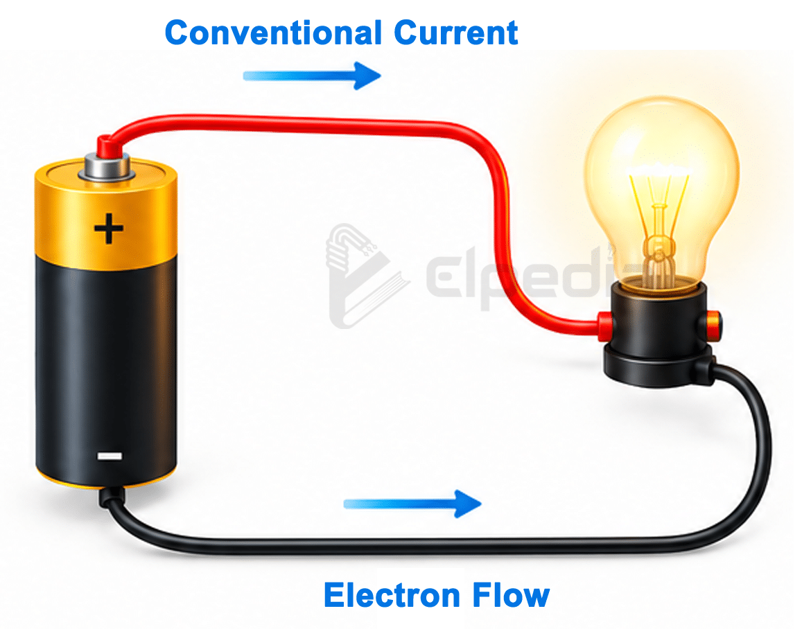
Conventional current is defined as the direction in which a positive charge would move in an external circuit. Therefore, in a circuit connected to a voltage source, conventional current flows from the positive terminal of the source, through the external circuit, to the negative terminal.
This direction represents the flow of positive charge and is the standard convention used in electrical and electronic circuit analysis.
Electron flow refers to the actual movement of free electrons in a metal conductor. Since electrons carry a negative charge, they move in the direction opposite to conventional current.
Therefore, in a metal wire, electrons flow from the negative terminal of a voltage source toward the positive terminal, while conventional current flows from positive to negative.
Ben Franklin established the convention for current direction in the mid-18th century, before the electron was discovered by J. J. Thomson in 1897. By the time the electron was discovered, electrical theory and circuit analysis had already been developed using the conventional current direction. As a result, the convention continued to be used.
Consider a battery connected to a lamp. Conventional current flows from the positive terminal of the battery, through the lamp, and back to the negative terminal.
At the same time, the electrons in the metal wires move in the opposite direction, from the negative terminal toward the positive terminal.
In electrolytes and plasmas, both positive and negative charge carriers can move simultaneously. However, the direction of conventional current is still defined based on the direction of positive charge movement. Thus, the contributions of all moving charge carriers combine to determine the net conventional current.
Direct Current (DC) and Alternating Current (AC)
Electric current can be classified as direct current (DC) or alternating current (AC) based on how its magnitude and direction vary with time.
DC Current
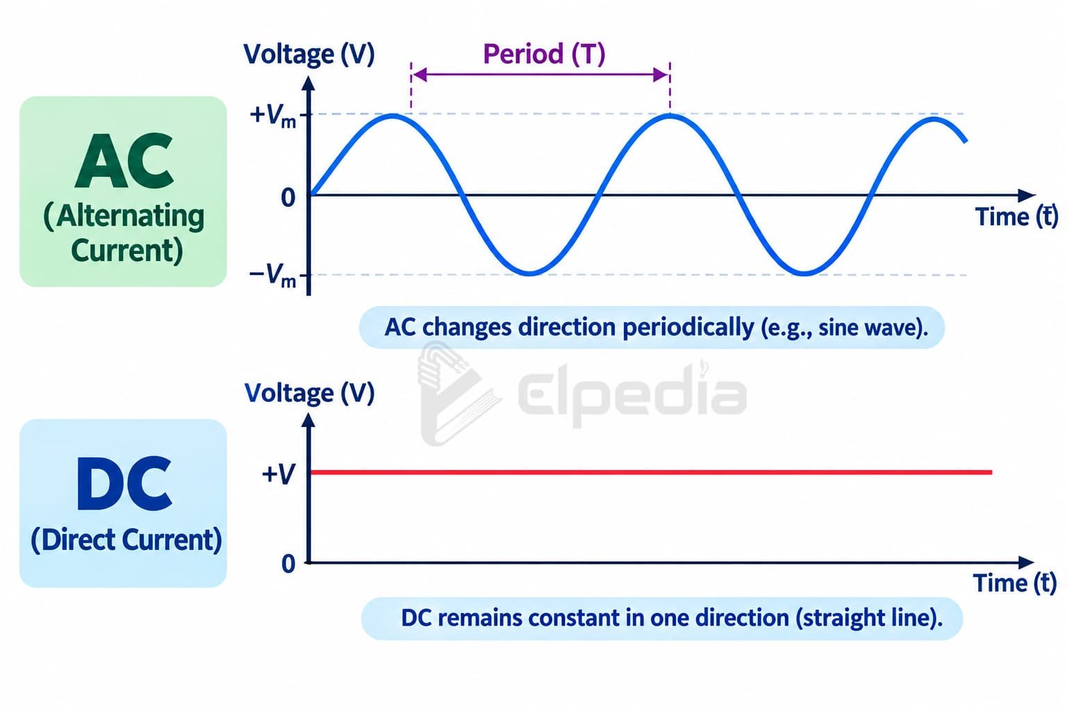
Direct current (DC) flows continuously in one direction. Its magnitude may remain constant or vary with time, but its direction does not reverse.
DC is commonly produced by batteries, solar cells, and DC power supplies.
Electronic circuits generally require a stable polarity and controlled voltage, making DC particularly suitable for powering electronic components and digital logic circuits.
It is also widely used in battery-powered devices, electric vehicles, and renewable energy systems.
Examples of DC sources include 1.5 V AA battery, 12 V car battery and USB power supplies, which provide DC output such as 5 V, 9 V, 12 V, 15 V, or 20 V depending on the charging standard.
Thus, the defining characteristic of DC is that the current maintains the same direction, even if its magnitude changes.
AC Current
Alternating current (AC) periodically changes both its magnitude and direction. In electrical power systems, AC is generally generated as a sinusoidal waveform.
The standard AC supply frequency is 50 Hz in India, most of Europe, and many other countries. Whereas, It is 60 Hz in North America and some other countries.
For example, the standard household supply in India is approximately 230 V AC at 50 Hz, while the standard supply in the United States is approximately 120 V AC at 60 Hz.
AC is widely used for domestic, commercial, and industrial power systems because it can be efficiently generated, transmitted, and distributed.
Although sinusoidal AC is commonly used in power systems, electric current can have many other waveforms in electronic circuits. Common examples include:
- Square wave – widely used in digital circuits and switching applications such as PWM motor control
- Triangular wave – used in signal generation and electronic circuits
- Sawtooth wave – used in timing, scanning, and signal-generation circuits
- Pulsed current – consists of regular or irregular pulses and is widely used in digital and power electronics
Therefore, AC does not necessarily have to be a sine wave. The term alternating current primarily refers to current that periodically reverses direction.
One major advantage of AC is that its voltage can be easily stepped up or stepped down using transformers. High-voltage AC can be transmitted over long distances with lower current for the same power, thereby reducing transmission losses.
For example, transformers are used to increase the voltage for transmission and reduce it again for distribution and consumer use.
In modern power systems, AC and DC are both important: AC is widely used for conventional power transmission and distribution, while DC is extensively used in electronics, batteries, solar PV systems, and many modern energy-storage and power-electronic applications.
Electric Current in a Closed Circuit
Electric current requires a complete conducting path to flow continuously. A basic electrical circuit consists of an energy source, a conducting path, a load, and usually a control device such as a switch.
The load opposes the flow of current and converts electrical energy into other forms, such as heat, light, or mechanical energy.
Electromotive force (EMF) is the energy supplied by an energy source to move a unit charge through the source from lower electric potential to higher electric potential. It is measured in volts (V).
A voltage source, such as a battery, generator, or solar cell, establishes a potential difference across the circuit. This potential difference creates an electric field in the conducting path, which causes the mobile charge carriers to drift and produce electric current.
Voltage is often compared to electrical pressure because it provides the driving force that causes charge carriers to move through a circuit.
Consider a simple circuit consisting of a 9 V battery, a switch, copper connecting wires, and a 100 Ω resistor.
- When the switch is open, the conducting path is broken. Therefore, there is no continuous path for current, and the current is zero.
- When the switch is closed, the circuit becomes complete and a steady current of I = 9/100 = 0.09 A flows through the resistor.
In a simple series circuit, the same current flows through every component in the conducting path. If the circuit is broken at any point, the current stops throughout the circuit.
Water-Flow Analogy
The operation of a closed electrical circuit can be compared to water flowing through a closed pipe. A pump provides the pressure that drives water through the pipe. If the pipe is cut or the path is opened, the continuous flow stops.
Similarly, a voltage source provides the driving force for charge movement in an electrical circuit. A complete conducting loop is necessary for sustained current flow.
Current Formulas, Ohm’s Law, and Power Relations
Electric current can be calculated using different formulas depending on the quantities known. The relationship between current, voltage, and resistance is given by Ohm’s Law:
![\[\boxed {I = \frac{V}{R}} \]](https://elpedia.com/wp-content/ql-cache/quicklatex.com-a2e4792d0656d90fbff6513ce163e870_l3.png "Rendered by QuickLaTeX.com")
where I is the current in amperes (A), V is the voltage in volts (V), and R is the resistance in ohms (Ω).
Ohm’s Law applies to ohmic or linear conductors, where the current is directly proportional to the applied voltage and inversely proportional to the resistance, provided the physical conditions remain constant.
Resistance opposes the movement of charge carriers through a resistor or other circuit element.
The fundamental definition of electric current is
![\[\boxed{ I = \frac{Q}{t} } \]](https://elpedia.com/wp-content/ql-cache/quicklatex.com-e1012d4058dd5a985fb206b3d1341b73_l3.png "Rendered by QuickLaTeX.com")
where Q is the charge transferred in coulombs (C) and t is the time in seconds (s).
This definition applies to all types of electrical devices, including nonlinear devices such as diodes, for which the simple form of Ohm’s Law does not apply.
Electrical power is related to voltage and current by
![\[P = V \times I \]](https://elpedia.com/wp-content/ql-cache/quicklatex.com-e03a587ca9be4b54a8ccca44c7d6814e_l3.png "Rendered by QuickLaTeX.com")
Therefore, current can be calculated as,
![\[\boxed{ I = \frac{P}{V}} \]](https://elpedia.com/wp-content/ql-cache/quicklatex.com-cb9148df874413a41279374541f5285f_l3.png "Rendered by QuickLaTeX.com")
Using Ohm’s Law, power can also be expressed as
![\[P = I^2 R \]](https://elpedia.com/wp-content/ql-cache/quicklatex.com-cad5dfd7f0dfaeed30e1bd6c5d0933c1_l3.png "Rendered by QuickLaTeX.com")
Therefore, the current equation becomes,
![\[\boxed{I = \sqrt{\frac{P}{R}}} \]](https://elpedia.com/wp-content/ql-cache/quicklatex.com-e5dc468da074a2034591fc7a121f7f1f_l3.png "Rendered by QuickLaTeX.com")
For AC circuits with purely resistive loads, the same power and resistance relationships can be used with RMS values of voltage and current. For example:
![\[\boxed{ I_{rms} = \frac{V_{rms}}{R}} \]](https://elpedia.com/wp-content/ql-cache/quicklatex.com-9b3898834ba559dd567f93a2e5b8bdcc_l3.png "Rendered by QuickLaTeX.com")
Solved Examples
Example 1: Current from voltage and resistance
Find the current when 24 V is applied across a 12 Ω resistor.
Given: V = 24 V, R = 12 Ω
Using Ohm’s Law:
![\[I = \frac{V}{R} = \frac{24}{12} \]](https://elpedia.com/wp-content/ql-cache/quicklatex.com-52a472d6ca8a6976977e9ccfb3cf1b0c_l3.png "Rendered by QuickLaTeX.com")
![\[I = 2 \, A \]](https://elpedia.com/wp-content/ql-cache/quicklatex.com-b716ad41ab77745b0b6c98d3328459a0_l3.png "Rendered by QuickLaTeX.com")
Example 2: Current from power and voltage
Find the current drawn by a 48 W load connected to a 24 V battery.
Given: P = 48 W, V = 24 V
Using the current formula derived from power,
![\[I = \frac{P}{V} = \frac{48}{24} \]](https://elpedia.com/wp-content/ql-cache/quicklatex.com-4e847cf8c4b83c338907aa4ff386620b_l3.png "Rendered by QuickLaTeX.com")
Example 3: Current from power and resistance
A 100 W heater has a resistance of 20 Ω. Calculate the current.
Given: P = 100 W, R = 20 Ω
Using the current equation derived from power and ohm’s law,
![\[I = \sqrt{\frac{P}{R}} =\sqrt{\frac{100}{20}}\]](https://elpedia.com/wp-content/ql-cache/quicklatex.com-e20d8a5bc881339fa43ce8d88b77bafc_l3.png "Rendered by QuickLaTeX.com")
![\[I = \sqrt{5} = 2.24 \, A\]](https://elpedia.com/wp-content/ql-cache/quicklatex.com-e1dad02baa80ff5348439a28895817e4_l3.png "Rendered by QuickLaTeX.com")
Drift Velocity and Current Density
There is an important difference between electric current and drift velocity. Electric current describes the amount of electric charge passing through a cross-sectional area of a conductor per unit time.
Drift velocity, on the other hand, is the average velocity with which charge carriers move through the conductor due to an applied electric field.
Although electric current can be several amperes, the drift velocity of electrons in a typical copper wire is very small—often on the order of millimetres per second. This corresponds to only a few metres per hour, depending on the current and the conductor’s cross-sectional area.
Current density is the amount of electric current flowing through a unit cross-sectional area of a conductor. It is represented by J and measured in amperes per square metre (A/m²).
For a uniform conductor,
![\[ J = \frac{I}{A} \]](https://elpedia.com/wp-content/ql-cache/quicklatex.com-07431c0ae537bf78596e1baf1b60053f_l3.png "Rendered by QuickLaTeX.com")
where I, J and A represents electric current (A), current density (A/m²) and cross-sectional area of the conductor (m²) respectively.
Current density provides a link between the macroscopic quantity of current and the microscopic movement of charge carriers within a conductor.
Why Does a Lamp Light Almost Instantly?
If electrons drift so slowly, why does a lamp light almost immediately after a switch is closed?
The answer is that the electric field propagates through the circuit very rapidly, rather than individual electrons travelling from the battery to the lamp at nearly the speed of light.
A useful analogy is a full ring of closely packed beads. If one bead is pushed, the force is transmitted through the ring, causing movement at the other side almost immediately, even though each individual bead moves only a small distance.
Similarly, when a circuit is completed, the electric field is established throughout the conducting path and causes charge carriers already present in the conductor to begin drifting.
The electrons are not consumed by the lamp. Instead, electrical energy is transferred to the load and converted into other forms, such as light and heat.
Types of Electric Current
Electric current can occur through different mechanisms. The main types include conduction current, convection current, and displacement current.
Conduction Current : It is produced by the directed movement of mobile charge carriers under the influence of an electric field.
- In metals, free electrons are the main charge carriers.
- In electrolytes, positive and negative ions carry the current.
- In semiconductors, both electrons and holes can contribute to current.
Conduction current is the most familiar type of current in electrical wires and electronic circuits.
Convection Current: It occurs when electric charges are transported by the bulk movement of matter.
For example, charged ions carried by a moving liquid or charged particles moving with air can produce convection current. This differs from conduction current because the charge carriers are transported along with the physical movement of the material.
Displacement Current : It was introduced by James Clerk Maxwell to account for the effects of a changing electric field, even in regions where there is no physical movement of charge through the medium.
Displacement current (Id) is given by:
![\[I_d = \varepsilon_0 \frac{d\phi_E}{dt} \]](https://elpedia.com/wp-content/ql-cache/quicklatex.com-80d13f6084f1e43982d948130b4f8976_l3.png "Rendered by QuickLaTeX.com")
where ε0 is the permittivity of free space and ΦE is the electric flux.
A common example is the region between the plates of a charging capacitor. No electrons physically cross the insulating gap between the plates, but the changing electric field between the plates produces a displacement-current term.
Displacement current is an essential part of the Ampère–Maxwell law and played a key role in Maxwell’s prediction of electromagnetic waves.
It is important to distinguish displacement current from eddy currents. Eddy currents are circulating currents induced within conducting materials by changing magnetic fields. They are a form of induced conduction current rather than displacement current.
Effects of Electric Current
When electric current passes through a conductor or solution, it produces three major observable effects, each with critical real-world applications.
Heating effect: Electric current generates heat in conductors. This is called Joule heating, and it occurs when current passes through a conductor with resistance. The heat produced is given by
![\[ H = I^2R t \]](https://elpedia.com/wp-content/ql-cache/quicklatex.com-b19fb41d1957c5a7a7b8cf1e47e49cef_l3.png "Rendered by QuickLaTeX.com")
For example, a current of 2 A flowing through a 5 Ω resistor for 60 seconds produces
![\[ H = 2^2 \times 5 \times 60 = 1200 J \]](https://elpedia.com/wp-content/ql-cache/quicklatex.com-effc7a2bc9e568ac4c31a64992cae473_l3.png "Rendered by QuickLaTeX.com")
The heating effect is used in electric heaters, toasters, electric irons, incandescent lamps, and electrical fuses.
Magnetic effect: When electric current flows through a conductor, it produces a magnetic field around the conductor.
The magnetic effect can be demonstrated by placing a compass near a current-carrying wire. The compass needle deflects due to the magnetic field produced by the current.
The direction of the magnetic field around a straight conductor can be determined using the right-hand thumb rule, based on the direction of conventional current.
This effect is widely used in electromagnets, relays, solenoids, transformers, generators, and dc motors.
Chemical effect: When electric current passes through an electrolyte, it causes the movement of ions and may produce chemical reactions at the electrodes. This process is known as electrolysis.
Electroplating is an application of the chemical effect of current, in which a thin layer of one metal is deposited on the surface of another material.
For example, copper can be deposited on a metal object by passing current through a copper sulfate (CuSO₄) solution. Current flowing through the electrolyte determines the rate of deposition, as per Faraday’s laws of electrolysis.
Other effects include current in biological systems (nerve impulses carry signals via tiny currents), resistive sensors like thermistors, and industrial processes such as electric arc furnaces.
Measurement of Electric Current
Electric current is measured using an ammeter, which is connected in series with the load. An ammeter has very low internal resistance, so it causes only a small change in the current flowing through the circuit.
To measure current with a digital multimeter:
- Select the current (A/mA/μA) measurement mode.
- Choose an appropriate range higher than the expected current.
- Open or break the circuit and insert the meter in series between two points.
- Connect COM terminal to the lower potential side and the A/mA terminal to the higher potential side.
Other Methods of Current Measurement
Besides conventional ammeters and multimeters, several other methods are used to measure electric current.
Safety precautions are critical:
Electrical Conductivity
Materials differ in their ability to conduct electric current mainly because of the availability and mobility of charge carriers within the material. Based on their electrical conductivity, materials are broadly classified as conductors, insulators, and semiconductors.
Conductors:
Conductors have a large number of free charge carriers that can move easily when an electric field is applied. Silver is the best conductor of electricity, but copper and aluminum are used more widely because they are less expensive and have suitable mechanical properties.
Copper is commonly used for electrical wiring because it has low resistivity, good mechanical strength, good ductility, and reasonable cost.
Insulators:
Insulators have very few free charge carriers, so they strongly resist the flow of electric current. Common insulating materials include plastic, glass, rubber, and dry wood.
Insulators are widely used for electrical insulation and safety, such as the plastic or rubber coating around electrical wires. They help prevent unwanted current flow and protect people from electric shock.
Semiconductors:
Semiconductors have electrical conductivity between that of conductors and insulators. Silicon and germanium are common semiconductor materials.
The electrical properties of semiconductors can be controlled by adding small amounts of impurities, a process known as doping. Doping produces n-type semiconductors (majority charge carriers are electrons) and p-type semiconductors (majority charge carriers are holes).
This ability to control conductivity makes semiconductors the basis of diodes, transistors, integrated circuits, and other electronic devices.
An intrinsic semiconductor has relatively low conductivity at low temperatures. Its conductivity generally increases as temperature increases because more charge carriers become available for conduction.
Temperature has different effects on different types of materials.
- In metals, resistivity generally increases as temperature increases. For example, the resistance of an incandescent lamp filament is much higher when it is hot than when it is cold.
- In semiconductors, resistivity generally decreases as temperature increases because the number of available charge carriers increases.
Some materials and systems exhibit special forms of electrical conduction.
Superconductors can exhibit virtually zero electrical resistance below a specific critical temperature. They are used in applications such as MRI systems, particle accelerators, and high-field electromagnets.
In a vacuum, electric current can also be produced when electrons are emitted from a surface by thermionic emission or field emission. This principle is used in devices such as vacuum tubes and electron guns.
The SI unit of electrical conductivity is the siemens per metre (S/m).
Solved Numerical Problems on Electric Current
The following solved problems illustrate the application of basic electric current formulas, Ohm’s law, electrical power, series circuits, and the heating effect of current.
Problem 1 (Definition-based): A charge of 50 C passes through a wire in 10 s. Find the electric current.
Given: Q = 50 C, t = 10 s
Solution:
![\[ I = \frac{Q}{t} = \frac{50}{10} \]](https://elpedia.com/wp-content/ql-cache/quicklatex.com-09f2502db6a48f70bdb3a79a97e12137_l3.png "Rendered by QuickLaTeX.com")
![\[ I = 5 \text{ A} \]](https://elpedia.com/wp-content/ql-cache/quicklatex.com-9ad89644fbff57cbb226e9de78b73f20_l3.png "Rendered by QuickLaTeX.com")
Problem 2 (Ohm’s Law + Power): A 6 Ω resistor is connected to a 12 V supply. Find the current flowing through the resistor and the power consumed.
Given: V = 12 V, R = 6 Ω
Solution:
![\[ \text{Current, I} = \frac{V}{R} = \frac{12}{6} \]](https://elpedia.com/wp-content/ql-cache/quicklatex.com-69c8d013977a858cb8412e38bd8813ba_l3.png "Rendered by QuickLaTeX.com")
![\[ I = 2\text{ A} \]](https://elpedia.com/wp-content/ql-cache/quicklatex.com-36a905aaaadfbfeace5fa5081e6d8878_l3.png "Rendered by QuickLaTeX.com")
![\[ \text{Power, P} = VI = 12 \times 2 \]](https://elpedia.com/wp-content/ql-cache/quicklatex.com-25e3765ba2b23bbcf097ea6ccc8164ff_l3.png "Rendered by QuickLaTeX.com")
![\[P = 24\text{ W} \]](https://elpedia.com/wp-content/ql-cache/quicklatex.com-54ccef5dcfab29853d3f2be5aff17700_l3.png "Rendered by QuickLaTeX.com")
Problem 3 (Series Circuit): Two resistors, R1 = 4 Ω and R2 = 8 Ω, are connected in series across a 12 V battery. Find the total current and the voltage drop across each resistor.
Given: R1 = 4 Ω, R2 = 8 Ω and V= 12 V
Solution :
For resistors connected in series, using the series resistance formula,
![\[R_{\text{total}} = R_1 + R_2 = 4+8\]](https://elpedia.com/wp-content/ql-cache/quicklatex.com-497108390bc4de0bb120f99825e15d3e_l3.png "Rendered by QuickLaTeX.com")
![\[R_{\text{total}}= 12\Omega \]](https://elpedia.com/wp-content/ql-cache/quicklatex.com-56b9256055e334e2fd2643bb1c1ea280_l3.png "Rendered by QuickLaTeX.com")
Now using the Ohm’s law equation, the total current can be determined as,
![\[I = \frac{V}{R_{\text{total}}} = \frac{12}{12}\]](https://elpedia.com/wp-content/ql-cache/quicklatex.com-aca28bf8cba686f0752acd74b376c7cf_l3.png "Rendered by QuickLaTeX.com")
![\[I = 1\text{ A}} \]](https://elpedia.com/wp-content/ql-cache/quicklatex.com-ada03010b59c80869add7298d6ac781a_l3.png "Rendered by QuickLaTeX.com")
The same current flows through every resistor in a series circuit.
Voltage drop across R1,
![\[V_1 = IR_1 1 \times 4\]](https://elpedia.com/wp-content/ql-cache/quicklatex.com-48857565a60f99cb53ddcfd66f77bb53_l3.png "Rendered by QuickLaTeX.com")
![\[V_1 = 4 \text{ V} \]](https://elpedia.com/wp-content/ql-cache/quicklatex.com-63e861f04b8057eabdd0bb67b7852da5_l3.png "Rendered by QuickLaTeX.com")
Voltage drop across R2
![\[V_2 = IR_2 = 1 \times 8\]](https://elpedia.com/wp-content/ql-cache/quicklatex.com-0dd5eb6df7aef5a3404f68c799790f4f_l3.png "Rendered by QuickLaTeX.com")
![\[V_2 = 8\text{ V} \]](https://elpedia.com/wp-content/ql-cache/quicklatex.com-6ec5c116975f36639bc04e7e98dfc879_l3.png "Rendered by QuickLaTeX.com")
Problem 4 (Heating Effect): Find the heat produced when a current of 3 A flows through a 10 Ω resistor for 2 minutes.
Given: I = 3 A, R = 10 Ω, t = 2 min = 120 s.
Solution :
![\[ H = I^2Rt = 3^2 \times 10 \times 120\]](https://elpedia.com/wp-content/ql-cache/quicklatex.com-562f9af36c7180322a6ead4080c23c17_l3.png "Rendered by QuickLaTeX.com")
![\[H = 10,800\text{ J} \]](https://elpedia.com/wp-content/ql-cache/quicklatex.com-6fb18274f3e5896e44cb486e25262bba_l3.png "Rendered by QuickLaTeX.com")
Problem 5 (Real-World Application): A 1000 W electric iron operates from a 230 V supply. Find its operating current and suggest a suitable fuse rating.
Given: P = 1000 W, V = 230 V
Solution:
![\[I = \frac{P}{V} = \frac{1000}{230} \]](https://elpedia.com/wp-content/ql-cache/quicklatex.com-1d1fe5979018c2e9c396d491a9025456_l3.png "Rendered by QuickLaTeX.com")
![\[I = 4.35 \text{ A} \]](https://elpedia.com/wp-content/ql-cache/quicklatex.com-163abbd32f733be6cd569204720b1aa5_l3.png "Rendered by QuickLaTeX.com")
The operating current of the iron is approximately 4.35 A. A 5 A fuse is a suitable nominal choice for this simplified example, provided it matches the appliance, wiring, plug, and applicable electrical standards.
Summary and Further Exploration
Electric current is the rate at which electric charge flows through a conductor or medium, measured in amperes. The essential formulas – I = Q / t, I = V / R, P = V × I, and H = I² R t – connect current to charge, voltage, resistance, and energy.
Electric current can be direct current (steady, one direction) or alternating current (periodically reversing) and produces heating, magnetic, and chemical effects that power virtually all modern technology.
Understanding conventional current flow versus electron flow, the role of conductive materials and insulating materials, and how to measure current safely with ammeters and multimeters gives you a strong foundation.
These concepts underpin advanced topics like network theorems, electromagnetism, AC circuit analysis, and power systems.
Explore more on Elpedia: dive into our guides on resistors and their combinations, power in AC circuits, and 150+ electrical engineering definitions to keep building your knowledge in electricity and magnetism.