Three-Phase Transformer Connections
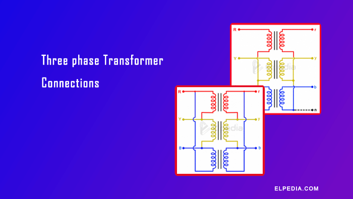
A three phase transformer is a device that steps line voltage up or down in three phase AC power systems.
Three-phase transformers distribute electrical power efficiently across transmission, distribution, and industrial plants, and have been a cornerstone of modern grids since widespread adoption in the 1920s–1930s.
Three-phase transformers can be connected in various configurations, and understanding these configurations is essential for anyone working with power systems.
These transformers come in two forms: a single integrated three phase unit with a common magnetic core (typically three or five limbs), or a bank of three single phase transformers wired together externally.
Utilities commonly use banks at the distribution level for flexibility-if one single phase transformer fails, it can be swapped out individually, reducing costs and downtime compared to replacing an entire unit.
The term phase transformer connections refers to how individual coil windings are linked-delta, wye (also called star), open delta, or zigzag-to form a working polyphase transformer.
Each transformer connection has unique advantages and disadvantages that must be considered during design and specification.
This article aims to be a practical, engineer-friendly reference for understanding how three phase transformer connections affect voltage ratios, current ratings, harmonics, and suitability for parallel operation.
Fundamentals of Three-Phase Transformer Connections
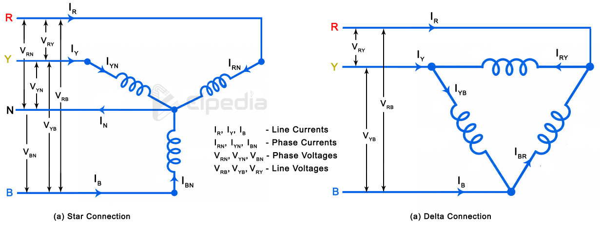
The primary and secondary windings of a three-phase transformer can be connected in either star (Y) or delta (Δ) configuration.
These connections determine the relationship between line voltage and phase voltage, as well as line current and phase current.
They also influence the availability of a neutral point, insulation requirements, and the transformer’s performance under unbalanced loads.
Line Voltage and Phase Voltage
The relationship between line voltage and phase voltage depends on the type of winding connection.
Winding Connection | Line Voltage | Phase Voltage | Relationship |
|---|---|---|---|
Star (Y) | | | |
Delta (Δ) | | | |


Star connection: In a star-connected winding, one end of each of the three phase windings is connected to a common point called the neutral point. The line voltage is √3 times the phase voltage.
Delta connection: In a delta-connected winding, the three phase windings are connected end-to-end to form a closed loop. In this connection, line voltage is equal to phase voltage.
For example, consider a three-phase transformer with a 400 V secondary line voltage:
- Star connection: The phase voltage is
 (approximately 230 V).
- Delta connection: The phase voltage is equal to the line voltage, which is 400 V.
 (approximately 230 V).
An important advantage of the star connection is that it provides a neutral point. This allows the transformer to supply both three-phase loads and single-phase loads.
Line Current and Phase Current
The relationship between line current and phase current also depends on the winding connection.
Winding Connection | Line Current | Phase Current | Relationship |
|---|---|---|---|
Star (Y) | | | |
Delta (Δ) | | | |


In a star connection, line current is equal to phase current. In a delta connection, line current is √3 times the phase current.
These relationships are important when selecting winding conductors and determining their current-carrying capacity.
Choice Between Star and Delta Connections
The selection of star and delta connections depends on the voltage level, insulation requirements, grounding arrangement, and nature of the connected loads.
In a star-connected winding with an earthed neutral, the voltage of each phase winding with respect to earth is equal to the phase voltage, which is  (57.7%) of the line voltage.
In contrast, in a delta-connected winding, each phase winding is subjected to the full line voltage.
During a single-line-to-ground fault in an unearthed delta system, the voltage of the healthy phase windings with respect to earth can rise to the line voltage.
Therefore, for the same system voltage, a star-connected winding requires fewer turns and less insulation than a delta-connected winding. This makes the star connection more economical for high-voltage applications.
In very high-voltage transformers, using a star connection on the high-voltage side can reduce the cost by approximately 10% compared with a delta connection.
A delta-connected primary with a star-connected secondary is commonly used when the transformer supplies both three-phase and single-phase loads.
When the secondary loads are unbalanced, zero-sequence currents are produced. The delta-connected primary provides a closed path for these currents to circulate within its windings.
As a result, zero-sequence currents do not flow through the primary line conductors. Only positive- and negative-sequence components appear in the primary line currents.
The sum of the three primary line currents is therefore zero:

A similar arrangement can be obtained using a star-connected primary if both primary and secondary neutral points are earthed.
However, this arrangement is generally less preferred because unbalanced secondary loads can cause zero-sequence currents to flow through the primary neutral and grounding system.
Three phase Transformer Connections
Star-Star (Y-Y) Connection
In a star-star connection, both the primary and secondary windings of a three-phase transformer are connected in star.
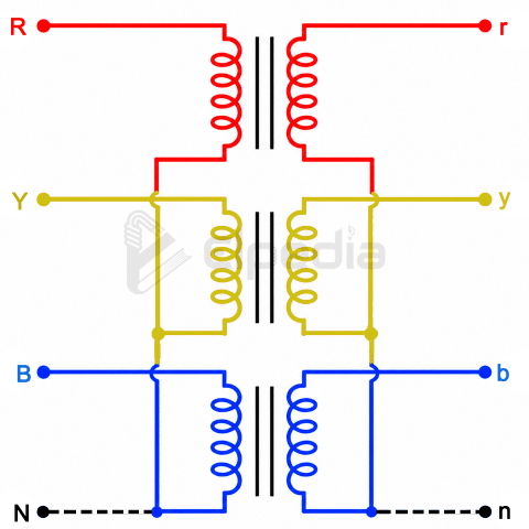
This arrangement is economical for high-voltage applications involving relatively low current because the phase voltage is only (1/\sqrt{3}) times the line voltage.
Due to this, each winding requires fewer turns and less insulation compared with a delta-connected winding of the same line voltage.
There is no phase displacement between the corresponding primary and secondary phase voltages, making the connection suitable for applications where zero phase displacement is required.
Neutral points are available on both the primary and secondary sides. These points can be used for grounding and for supplying single-phase loads.
However, without a delta-connected tertiary winding or an alternative path for third-harmonic currents, the magnetic flux waveform may become distorted, resulting in distortion of the induced voltage waveforms.
Delta-Delta (Δ–Δ) Connection
In a delta-delta connection, both the primary and secondary windings of a three-phase transformer are connected in delta.
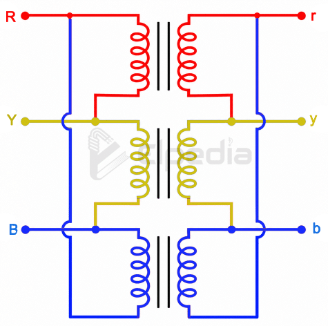
This arrangement is commonly used in low-voltage, high-current applications, particularly where continuity of power supply is important.
One of the major advantages of this connection is that the transformer can continue supplying three-phase power even if one of its three windings becomes faulty or is removed from service.
In this condition, the transformer operates as an open-delta (V–V) connection. It maintains the correct three-phase voltage and current relationships, but its total capacity is reduced to approximately 57.7% of its original three-phase rating.
There is no phase displacement between the corresponding primary and secondary line voltages in a delta-delta connection.
The delta-delta connection provides a closed path for third-harmonic currents to circulate within the windings. This helps reduce harmonic distortion in the output voltage and maintains a nearly sinusoidal waveform.
It also performs well under unbalanced load conditions, making it suitable for large industrial loads and conventional power distribution systems.
The phase current in each winding is times the line current. Therefore, the winding conductors can have a smaller cross-sectional area for a given line current compared with a star-connected winding.
Each phase winding in a delta connection is subjected to the full line voltage. Therefore, more insulation is required compared with a star-connected winding operating at the same line voltage.
A delta connection does not provide a neutral terminal. Consequently, it cannot directly supply single-phase loads that require a neutral connection.
Since there is no neutral point, grounding arrangements require additional consideration. During a single-line-to-ground fault, the voltage of the healthy phase windings with respect to earth may rise to the full line voltage in an unearthed delta system.
Star-Delta (Y – Δ) Connection
In a star-delta connection, the primary winding is connected in star, while the secondary winding is connected in delta.
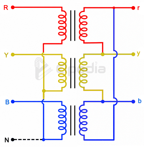
This arrangement is commonly used in step-down transformers, particularly at the receiving end of high-voltage transmission lines.
The primary star point is generally grounded to provide a neutral reference and improve the grounding arrangement of the high-voltage system.
Since the primary winding is star-connected, the voltage across each primary phase winding is only (57.7%) of the primary line voltage. Therefore, the insulation requirement is reduced, resulting in lower transformer manufacturing costs for high-voltage applications.
The line voltage ratio of a star-delta transformer is related to its winding turns ratio by a factor of .
Additionally, the secondary line voltages have a phase displacement of either +30° or −30° with respect to the primary line voltages, depending n the winding polarity and connection arrangement.
Delta-Star (Δ–Y) Connection
In a delta-star connection, the primary winding is connected in delta, while the secondary winding is connected in star.
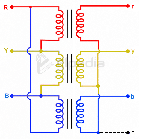
This configuration is commonly used in step-up transformers at generating stations and at the beginning of high-voltage transmission systems.
Since the secondary is star-connected, the voltage across each phase is only (57.7%) of the secondary line voltage. This reduces the insulation requirement and makes the arrangement economical for high-voltage applications.
The neutral point in the secondary can be grounded to maintain a stable neutral voltage even under unbalanced load conditions.
The delta-connected primary also provides a closed path for third-harmonic currents to circulate within the windings, thereby reducing harmonic distortion in the output voltage.
The line voltage ratio of a delta-star transformer is  times its winding turns ratio. The secondary line voltages also have a phase displacement of either +30° or −30° with respect to the primary line voltages, depending on the winding connections.
The grounded neutral on the secondary side allows the transformer to supply a three-phase, four-wire distribution system. This makes it suitable for supplying both three-phase equipment and single-phase loads.
For example, an 11 kV/433 V distribution transformer provides a four-wire secondary supply consisting of three phase conductors and one neutral conductor.
The three phase equipment can be connected to the line wires supplied at 415 V whereas the single phase loads can be connected between line and neutral to be supplied at 230 V.
Delta-star and star-delta transformers generally cannot be operated in parallel with star-star or delta-delta transformers, even if their voltage ratios are identical.
This is because they have a 30° phase displacement between their corresponding primary and secondary line voltages, whereas star-star and delta-delta connections have zero phase displacement.
Operating transformers with different phase displacements in parallel can result in circulating currents and improper load sharing. Therefore, transformers must have compatible vector groups for parallel operation.
Three-phase transformer connections play an important role in power transmission and distribution. The selection of a suitable connection depends on the voltage level, load requirements, insulation, grounding, and operating conditions.
In addition to the four main connections discussed in this article (Star-Star, Delta-Delta, Star-Delta, and Delta-Star), two other important connections are the Open-Delta (V-V) connection and the Scott connection. These connections have specific applications in three-phase power systems and are discussed in detail in the next article.