Comparison between Autotransformer and Two Winding Transformer
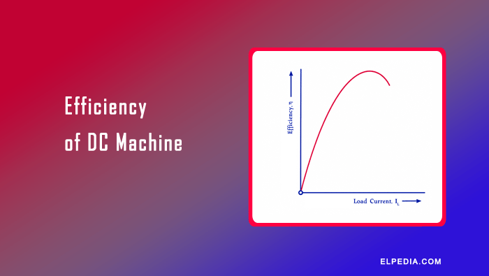
An autotransformer and a two-winding transformer are both used to change AC voltage levels, but they differ in construction, working principle, and performance.
A two-winding transformer has separate primary and secondary windings, providing electrical isolation between the input and output circuits.
In contrast, an autotransformer uses a single winding with a common section shared by both circuits, making it more compact and economical.
The main differences between these transformers can be understood by comparing their conductor material requirements, core size, cost, losses, efficiency, leakage impedance, and voltage regulation.
Understanding these differences helps in selecting the appropriate transformer for applications such as voltage regulation, motor starting, and power distribution.
In this article, let us learn the comparison between auto transformer and two winding transformer in different parameters.
VA Ratings
A two-winding transformer can be connected as an autotransformer by using a portion of its winding as a common winding.
To understand the advantage of this connection, let us compare the VA ratings of the transformer in both configurations.
When the transformer operates as a conventional two-winding transformer, the voltage across the series winding is (V1 – V2). Therefore, its VA rating is

When the same transformer is connected as an autotransformer, its VA rating is determined by the input or output voltage and current.

where V1 and V2 are the input and output voltages, respectively, and I1 and I2 are the corresponding currents.
The ratio of the VA rating as an autotransformer to that as a two-winding transformer is
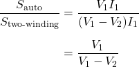
We know the transformation ratio is,

Therefore,
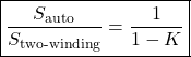
This expression applies to the step-down autotransformer configuration, where V1 > V2.
The equation shows that a transformer can handle a higher VA rating when connected as an autotransformer than when it operates as a conventional two-winding transformer, provided the winding voltage and current ratings are respected.
This improvement occurs because a portion of the power is transferred directly through electrical conduction between the input and output, while the remaining portion is transferred through electromagnetic induction.
Consequently, the windings need to transform only a fraction of the total power, allowing the same transformer windings to handle a higher overall VA rating.
Conductor Material Requirements
The amount of conductor material required for a transformer depends on the cross-sectional area and length of the winding conductor.
The cross-sectional area is determined by the current carried by the conductor, while its length depends on the number of turns.
Therefore, for the same conductor material and current density, the weight of conductor is proportional to the product of the number of turns and the current.
For a conventional two-winding transformer, the total weight of conductor material required for the primary and secondary windings is proportional to

For an ideal transformer, the ampere-turns of the primary and secondary windings are approximately equal,

Hence,

In an autotransformer, a portion of the winding is shared by the primary and secondary circuits. The top section has (N1-N2) turns and carries current I1.
The bottom section has N2 turns and carries the current difference (I2-I1), assuming the step-down configuration and the indicated current directions.
Therefore, the weight of conductor material required for the autotransformer is proportional to

Expanding the expression gives

Since N2I2=N1I1,

For the same input VA rating, output VA rating, and voltage ratio, the ratio of conductor material required by the autotransformer to that required by the two-winding transformer is

We know the transformation ratio is,
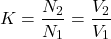
Therefore,
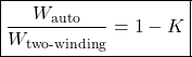
The percentage saving in conductor material is

The equations show that an autotransformer requires less conductor material than a conventional two-winding transformer for the same voltage and power ratings, under the assumptions used in this comparison.
The saving increases as the transformation ratio approaches unity.
When K approaches 1, the required conductor material approaches zero in this idealized comparison because the input and output voltages become nearly equal, reducing the voltage difference that the transformer must provide.
At exactly K=1, no voltage transformation is required.
Conversely, when K is very small, the saving in conductor material is relatively low.
In such applications, a conventional two-winding transformer may be preferable, particularly when electrical isolation between the input and output circuits is required.
Core Size and Weight
In an autotransformer, the voltage per turn and the maximum magnetic flux remain the same as in the corresponding two-winding transformer operating under the same conditions. Therefore, the required core cross-sectional area remains essentially unchanged.
However, the autotransformer uses less conductor material because a portion of the winding is common to both the primary and secondary circuits.
This reduces the required winding window area, which can allow a shorter core structure. Consequently, the overall core size and weight may be reduced, depending on the transformer design.
Cost
An autotransformer can reduce manufacturing costs because it requires less conductor material and may also require less core material.
However, the total cost saving is smaller than the percentage reduction in conductor material because the core still accounts for a significant portion of the transformer’s overall cost.
For a transformation ratio of approximately 0.5, the theoretical saving in conductor material is about 50% compared with a two-winding transformer of equivalent ratings.
Under suitable design and cost conditions, the total cost of an autotransformer may be approximately 65–70% of that of a comparable two-winding transformer.
The actual cost depends on the voltage ratio, power rating, insulation requirements, and construction.
Losses and Efficiency
An autotransformer generally requires less conductor material than a conventional two-winding transformer of the same rating.
This can reduce winding resistance and, consequently, copper losses. Its core losses may also be lower if the design uses a smaller core or less core material while maintaining the required magnetic performance.
Because of these reduced losses, an autotransformer can achieve higher efficiency than a comparable two-winding transformer.
This advantage is particularly significant when the input and output voltages are relatively close, allowing a substantial reduction in the amount of power transferred through electromagnetic induction.
Leakage Impedance and Voltage Regulation
An autotransformer generally has lower winding resistance because it requires less conductor material than a comparable two-winding transformer.
Since a portion of the winding is shared by the primary and secondary circuits, the leakage flux is also generally reduced, resulting in lower leakage reactance.
Consequently, an autotransformer typically has lower leakage impedance and better voltage regulation than a conventional two-winding transformer of the same VA rating.
This means that its output voltage experiences a smaller change when the load varies, provided both transformers are compared under equivalent operating conditions.