Construction, Working and Applications of Autotransformer
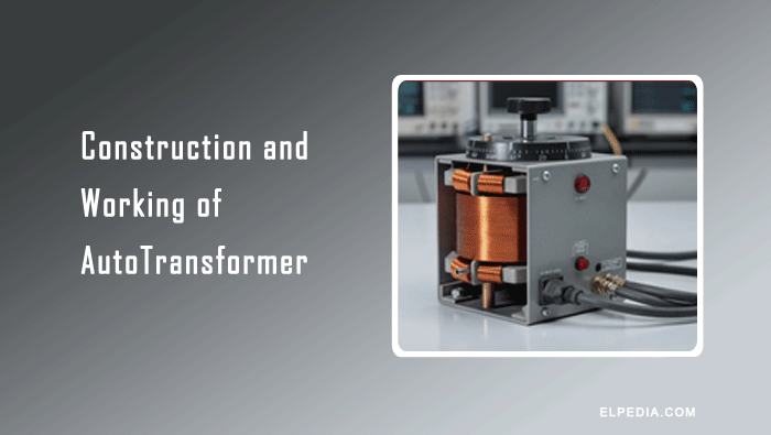
An autotransformer is a type of electrical transformer that uses only a single continuous winding to perform voltage transformation between its input and output terminals.
Unlike a conventional transformer – which has two separate windings that are electrically insulated from each other – an auto transformer shares part of the same winding for both primary and secondary circuits.
This means there is a direct connection between the supply and the load, with no galvanic separation.
This article covers the complete construction of auto transformer designs, their working principle, key advantages, and the practical applications where they outperform ordinary two winding transformers.
Construction of Autotransformer
An autotransformer consists of three main parts: a magnetic core, a single winding, and an insulation system.
The magnetic core is made of thin laminated silicon steel sheets. These sheets are stacked together to provide a low reluctance path for magnetic flux and reduce core losses. Proper core design prevents magnetic saturation and improves transformer performance.
The commonly used core shapes are:
- Core-type: The winding is placed around the core limbs. This construction is widely used in power transformers.
- Shell-type: The core surrounds a major part of the winding and provides good mechanical support.
- Toroidal type: The core is ring-shaped, and the winding is distributed around it. This design offers low leakage flux, quiet operation, and compact construction.
Unlike a conventional transformer, which has separate primary and secondary windings, an autotransformer uses a single continuous winding for both the input and output. The winding is made of copper or aluminium and is wound around the core.
Consider an autotransformer with three terminals: A, B, and C. The entire winding between terminals A and B forms the primary winding and consists of N1 turns.
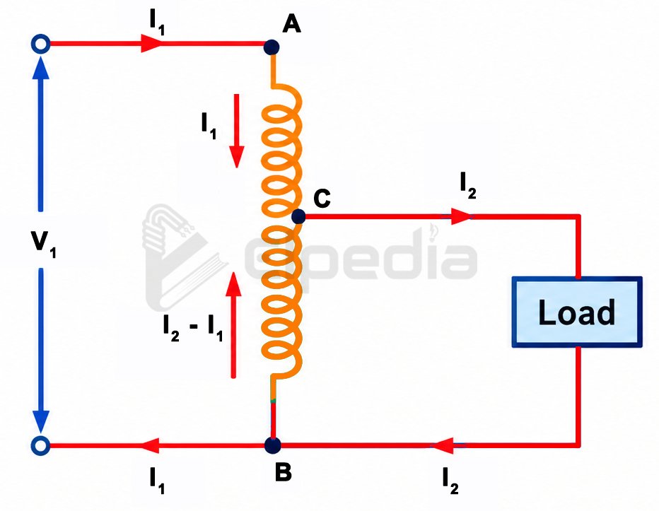
When the input voltage V1 is applied across these terminals, a portion of the same winding between terminals B and C, containing N2 turns, provides the secondary voltage V2.
Assuming that the voltage drops due to the winding impedance are negligible, the voltage per turn is V1/N1. Therefore, the output voltage across terminals B and C is given by

When the supply is connected across the full winding AB and the load is connected across CB, the output voltage is lower than the input voltage. Therefore, the autotransformer operates as a step-down autotransformer.
When the connections are arranged so that the output voltage is greater than the input voltage, it operates as a step-up autotransformer.
The tapping points may be fixed to provide specific output voltages. In a variable autotransformer, commonly called a Variac, a movable brush slides over the winding to obtain a continuously adjustable output voltage within its designed range.
The winding is insulated using enamel coating, while insulating paper or other suitable materials are used between winding layers.
Varnish may also be applied to improve insulation and mechanical strength. Depending on the voltage and power rating, an autotransformer may be air-cooled or oil-immersed.
Working of Autotransformer
The working principle of an autotransformer is based on Faraday’s law of electromagnetic induction, similar to that of a conventional transformer.
However, an auto transformer transfers electrical power through both electromagnetic induction and direct electrical conduction because the primary and secondary circuits share a common winding.
When an AC voltage is applied across the full winding AB, an alternating current produces a changing magnetic flux in the laminated core. This flux links the turns of the winding and induces an EMF in each turn.
Therefore, the output voltage obtained across the tapped section BC depends on the number of turns in that section.
The main difference between an autotransformer and a conventional transformer is that they share a portion of the same winding.
As a result, part of the electrical power is transferred directly through the common winding, while the remaining portion is transferred through electromagnetic induction.
This arrangement reduces the amount of power that must be transferred magnetically, resulting in lower losses and higher efficiency.
For example, consider a 240/200 V step-down autotransformer. The input voltage is 240 V, and the output voltage is 200 V. The voltage difference is 40 V.
In an ideal auto transformer, only a fraction of the total power corresponding to this voltage difference is transferred through electromagnetic induction, while the remaining power is transferred conductively through the common electrical connection.
Advantages of Autotransformers
Limitations of Auto transformers
Applications of Auto transformers
Despite their limitations, auto transformers are widely used in applications that require efficient voltage conversion or adjustment without electrical isolation between the input and output circuits.
1. Motor Starting: Autotransformers are used in autotransformer starters to start large induction motors at a reduced voltage. Three-phase autotransformer starters, such as Korndörfer starters, typically use 50%, 65%, or 80% voltage taps to reduce the starting current and limit mechanical stress on the motor and driven equipment.
2. Power Systems and Distribution: Autotransformers are used to interconnect power systems operating at different voltage levels, particularly when the voltage difference is relatively small. For example, they can be used to connect 230 kV and 115 kV transmission networks.
3. Laboratory and Testing Applications: Variable autotransformers provide adjustable AC output voltage. They are widely used in electrical laboratories, testing facilities, calibration setups, and educational demonstrations where a variable AC supply is required.
4. Industrial Applications: Autotransformers are used to adjust supply voltages for industrial equipment and machinery. They can provide voltage adjustment for suitable CNC machines, manufacturing equipment, and other electrical loads that require a specific operating voltage.
5. Renewable Energy Systems: Autotransformers can be used in certain solar power and other renewable energy installations to match AC voltage levels between power conversion equipment and the electrical grid, where appropriate. Their use depends on the system configuration and voltage requirements.
6. Voltage Regulation and Impedance Matching: Autotransformers are used as voltage regulators in distribution systems and as impedance-matching devices in selected electrical and electronic circuits. Their high efficiency and compact design make them suitable for applications where electrical isolation is not required.