
Basic Terms and Definitions in Magnetic circuit
Key Takeaways
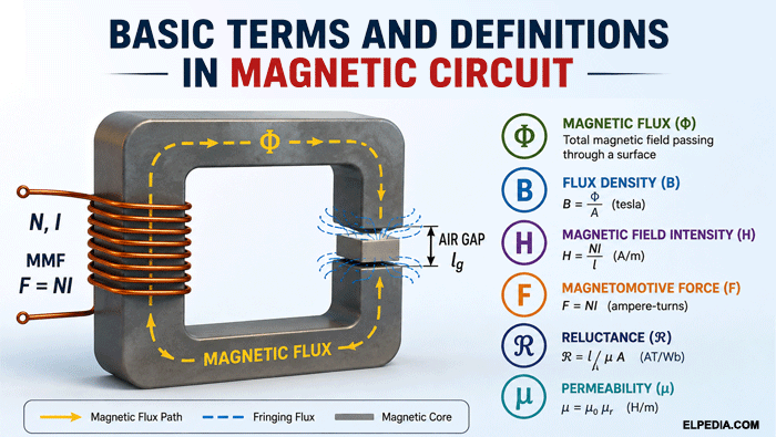
- A magnetic circuit is a closed path for magnetic flux Φ (measured in webers), directly analogous to an electric circuit that carries current I (measured in amperes). Magnetic circuits are essential in transformers and motors, where they help control and guide magnetic flux in electrical devices.
- The core relations you need to remember are: Φ = B·A, B = μH, MMF F = NI, and Hopkinson’s law F = Φℜ, with reluctance ℜ = ℓ / (μA).
- Each magnetic quantity has an electric-circuit counterpart: magnetic flux Φ maps to current I, magnetomotive force MMF maps to electromotive force EMF, reluctance maps to resistance, and permeance maps to conductance.
- Real magnetic circuits include effects like leakage flux, fringing at air gaps, and nonlinear B–H behavior (saturation and hysteresis) that simple formulas cannot fully capture.
- Mastering these basic definitions in magnetic circuit analysis is the foundation for designing efficient electrical machines, inductors, and power conversion devices.
Introduction to Magnetic Circuits
A magnetic circuit is a closed path in which magnetic flux Φ is established and guided, typically by a magnetizing coil carrying electric current or by a permanent magnet.
Just as electrical circuits provide a route for current to flow through conductors, magnetic circuits provide a route for flux to travel through magnetic cores, air gaps, and free space.
The concept became standard in electrical engineering during the late 19th and early 20th century, when engineers needed practical tools to analyze and design transformers, electric motors, generators, and relays.
Magnetic circuits are crucial for efficient flux distribution and they minimize energy loss in electrical systems. They are also used in generators to produce electromotive force through electromagnetic induction.
In this guide, you will find precise definitions, equations, and units for all the essential terms: magnetic flux, magnetic flux density, magnetomotive force MMF, magnetic field intensity, reluctance, permeance, permeability, relative permeability, magnetization, magnetic path, air gap, leakage flux, and fringing.
You will also see how circuit diagrams for magnetic circuits mirror those for electrical circuits, and where the analogy breaks down.
Fundamental Concepts: Magnetic Field, Lines of Force, and Magnetic Flux
A magnetic field is a region of space in which magnetic forces act on moving electric charges, magnetic materials, or a magnetic pole. It can be visualized using magnetic field lines, also known as magnetic lines of force.
Magnetic field lines form continuous, closed loops. Outside a magnet, they emerge from the north pole and enter the south pole, as shown in the below picture. Inside the magnet, they travel from the south pole back to the north pole, completing the closed loop.
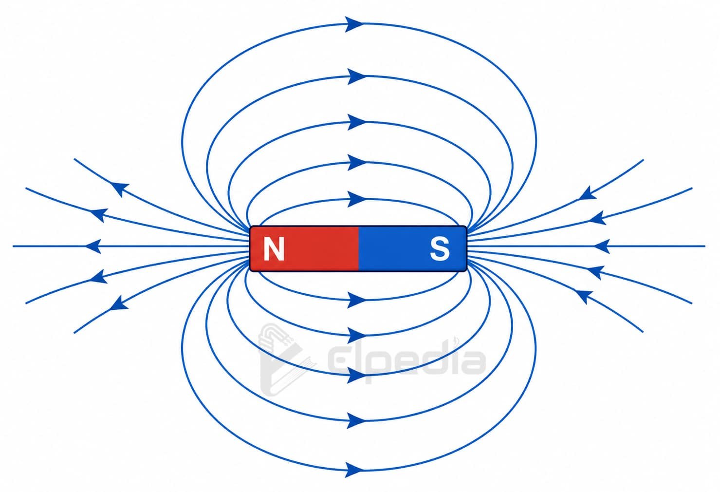
Magnetic field lines never intersect each other. The density of these lines indicates the relative strength of the magnetic field: closely spaced lines represent a stronger magnetic field, while widely spaced lines represent a weaker field.
A magnetic field can be visualized around a current-carrying conductor or a permanent magnet. If a unit north magnetic pole is placed in a magnetic field, it experiences a force in the direction of the magnetic field lines.
Magnetic flux (Φ) is the total amount of magnetic field passing through a given surface. It can be represented by the total number of magnetic field lines passing through that surface. The SI unit of magnetic flux is the weber (Wb), which is equivalent to volt-second (vs).
Mathematically, flux is the surface integral of magnetic flux density over the given area
![\[\Phi = \iint_S \mathbf{B}\cdot d\mathbf{A} \]](https://elpedia.com/wp-content/ql-cache/quicklatex.com-3607e7ee52607f9185b9d96c3a0a62f6_l3.png "Rendered by QuickLaTeX.com")
For a uniform magnetic flux density over a flat surface with cross-sectional area (A), the magnetic flux is given by
![\[\Phi = BA\cos\theta \]](https://elpedia.com/wp-content/ql-cache/quicklatex.com-78371c23dc13058a8b03b31262f71d1f_l3.png "Rendered by QuickLaTeX.com")
where B is the magnetic flux density and θ is the angle between the magnetic flux density vector and the normal (perpendicular) to the surface.
In magnetic circuits, the magnetic flux is generally assumed to be approximately uniform across the cross-sectional area of the core. When the flux is perpendicular to the cross-sectional area, (θ = 0°), and the above equation simplifies to
![\[\Phi = BA\]](https://elpedia.com/wp-content/ql-cache/quicklatex.com-dc338c9068963c827ae14adb0ebdb655_l3.png "Rendered by QuickLaTeX.com")
This assumption simplifies the analysis of magnetic circuits by allowing the magnetic flux to be considered as flowing along a well-defined path through the core.
Magnetic flux is measured in webers (Wb). In magnetic circuit analysis, magnetic flux is analogous to electric current in an electric circuit.
Magnetic Flux Density (B)
Magnetic flux density (B) indicates how concentrated the magnetic flux is over a given area. In basic electrical engineering, B is often referred to as the magnetic field or magnetic induction.
Magnetic flux density is defined as the magnetic flux per unit area perpendicular to the direction of the flux, expressed as
![\[B = \frac{\Phi}{A}\]](https://elpedia.com/wp-content/ql-cache/quicklatex.com-c43b0172ffbd7678c22212b6474c8df6_l3.png "Rendered by QuickLaTeX.com")
where B is the magnetic flux density, Φ is the magnetic flux, and A is the cross-sectional area perpendicular to the flux. The SI unit of magnetic flux density is the tesla (T), where 1 T = 1 Wb/m².
Magnetic flux density is technically a vector quantity, having both magnitude and direction. However, in magnetic circuit analysis, its magnitude is generally considered, and is often assumed to be approximately uniform across the cross-section of the core or air gap.
For the same applied magnetomotive force, ferromagnetic materials such as soft iron and silicon steel can support much higher flux densities than air or free space because of their much higher permeability.
However, the flux density must be kept below the saturation level of the magnetic material. For typical transformer steels, saturation occurs at approximately 1.5–2.0 T, depending on the material and operating conditions.
Beyond the saturation region, a small increase in magnetizing force produces only a small increase in flux density, resulting in increased magnetizing current, higher losses, and waveform distortion.
The relationship between magnetic flux density (B) and magnetic field intensity (H) is represented by the B-H curve. It is an important tool for analyzing the magnetic properties of materials and selecting a suitable operating point for magnetic cores.
Magnetic Field Strength / Magnetic Field Intensity (H)
It is important to distinguish between magnetic flux density (B) and magnetic field intensity (H). While B represents the actual flux density established within a material, H represents the magnetizing force produced by electric current or magnetomotive force.
Thus, H is primarily determined by the current and the geometry of the magnetic circuit, whereas B also depends on the magnetic properties of the material.
Magnetic field intensity (H) is defined as the magnetizing force per unit length along the magnetic path. Its SI unit is ampere per metre (A/m).
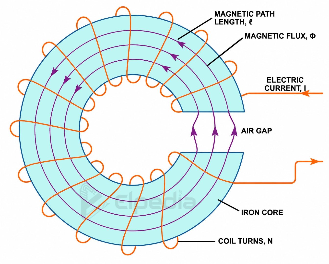
For a uniform section of a magnetic circuit, such as a solenoid wound around an iron core, as shown in the below figure, H is given by,
![\[ H = \frac{NI}{\ell} \]](https://elpedia.com/wp-content/ql-cache/quicklatex.com-e39dcf4ce8bcef02d2dce83b1b2d4202_l3.png "Rendered by QuickLaTeX.com")
The relationship between B and H is determined by the permeability (μ) of the material,
![\[B = \mu H \]](https://elpedia.com/wp-content/ql-cache/quicklatex.com-32ccbe4a3e2c0d55cced616f8940e127_l3.png "Rendered by QuickLaTeX.com")
For ferromagnetic materials, permeability is generally nonlinear and varies with the operating point on the material’s B-H curve. In free space, the relationship becomes
![\[ B = \mu_0 H \]](https://elpedia.com/wp-content/ql-cache/quicklatex.com-eb0cdfa06d6d7ccdb213250b82348fec_l3.png "Rendered by QuickLaTeX.com")
where μ₀ is the permeability of free space, with a value of μ₀ = 4π × 10⁻⁷ H/m. For most basic electrical engineering calculations, air can be treated as having approximately the same permeability as free space.
Magnetic Flux, MMF, and Hopkinson’s Law in a Magnetic Circuit
Hopkinson’s law is the fundamental law used to analyze magnetic circuits, named after John Hopkinson. However, it was earlier formulated by Henry Augustus Rowland and hence it is also called Rowland’s Law.
It plays a role similar to Ohm’s law in electrical circuits by relating the magnetic flux, magnetomotive force, and reluctance of a magnetic circuit.
In a magnetic circuit, magnetic flux (Φ) is analogous to electric current (I) in an electrical circuit. Just as electric current flows through an electrical circuit, magnetic flux is established along the magnetic path of a magnetic circuit.
Magnetomotive force (MMF) is the driving force that establishes magnetic flux in a magnetic circuit, represented by F. It is analogous to electromotive force (EMF) in an electrical circuit. The SI unit of MMF is the ampere-turn (At), and it is given by F = NI.
Hopkinson’s law states that the MMF is equal to the product of magnetic flux and magnetic reluctance, given by F = Φℜ, where ℜ is the reluctance of the magnetic circuit.
This is directly analogous to V = IR. Magnetic circuits are governed by Hopkinson’s law, similar to Ohm’s law for electric circuits.
In the more general form from electromagnetic theory, MMF is defined as the line integral of magnetic field intensity (H) around the magnetic path.
![\[ F = \oint \mathbf{H}\cdot d\mathbf{l} \]](https://elpedia.com/wp-content/ql-cache/quicklatex.com-08ef169974578c5228eae6c9453d679b_l3.png "Rendered by QuickLaTeX.com")
For a uniform magnetic path, this simplifies to F ≈ Hℓ.
Magnetomotive Force (MMF) in Detail
Magnetomotive force (MMF) is the driving force that establishes and maintains magnetic flux in a magnetic circuit. It is produced by an electric current flowing through a magnetizing coil or by the magnetization of a permanent magnet.
MMF drives magnetic flux through a magnetic circuit in much the same way that voltage drives electric current through an electrical circuit.
The basic engineering formula for MMF is F = N × I ampere turns, where F represents the MMF, N represents the number of turns in the coil and I is the current.
Although the “gilbert” was historically used as a unit of MMF in the CGS [Centimeter-Gram-Second] system, modern electrical engineering generally uses ampere-turns (AT).
The relation between MMF and field strength H can be expressed as: for a uniform section of length ℓ, F = Hℓ or H = F / ℓ. This ties magnetic field intensity directly to MMF and the length of the magnetic path.
When a magnetic circuit consists of several sections, such as an iron core and an air gap, the total MMF is equal to the sum of the MMF drops across the individual sections, given by
![\[F_{\text{total}} = \sum_i H_i\ell_i\]](https://elpedia.com/wp-content/ql-cache/quicklatex.com-ee8ab4ac523692db8a0fe8c12dea2c48_l3.png "Rendered by QuickLaTeX.com")
Since the MMF drop across each section can also be expressed in terms of flux and reluctance,
![\[ F_{\text{total}} = \Phi\sum_i\mathcal{R}_i \]](https://elpedia.com/wp-content/ql-cache/quicklatex.com-57592af6b28cb1cf4fefefd42374a1ff_l3.png "Rendered by QuickLaTeX.com")
This is analogous to an electrical circuit in which the total voltage is equal to the sum of the voltage drops across individual resistances connected in series.
Consider a coil with 500 turns carrying a current of 1.2 A. The MMF produced by the coil is:
![\[F = N\,I \]](https://elpedia.com/wp-content/ql-cache/quicklatex.com-c98ec104e499e95a858e9e97db0cd231_l3.png "Rendered by QuickLaTeX.com")
![\[F = 500\times1.2 = 600 \,\text{AT} \]](https://elpedia.com/wp-content/ql-cache/quicklatex.com-301d2a0bf79fcb8063808f628d1c9e12_l3.png "Rendered by QuickLaTeX.com")
Therefore, the coil produces an MMF of 600 ampere-turns. This MMF is distributed across the different sections of the magnetic circuit, such as the core and air gap, according to their respective reluctances.
Reluctance (ℜ) and Permeance (Λ)
Reluctance plays the same role in a magnetic circuit that electrical resistance plays in an electric circuit: it opposes the establishment of flux.
However, unlike resistance, reluctance does not dissipate energy as heat in steady-state operation. Energy is stored in magnetic fields, while energy is dissipated as heat in electric circuits.
Magnetic reluctance ℜ is the opposition offered by the magnetic circuit to the establishment of magnetic flux in a circuit. Reluctance in magnetic circuits is analogous to resistance in electric circuits. Reluctance is measured in Ampere-turns per Weber (AT/Wb).
For a uniform section of a magnetic circuit, reluctance is given by:
![\[\mathcal{R}=\frac{\ell}{\mu A} \]](https://elpedia.com/wp-content/ql-cache/quicklatex.com-222d4adfa6ba2da6a02e9fe2e3adc1f1_l3.png "Rendered by QuickLaTeX.com")
where ℓ is the mean path length, A is the cross sectional area, μ is absolute permeability. The absolute permeability is given by,
![\[ \mu=\mu_0\mu_r \]](https://elpedia.com/wp-content/ql-cache/quicklatex.com-457c58f8df0f302bd3df0b0174e59cc9_l3.png "Rendered by QuickLaTeX.com")
where μ0 is the permeability of free space and μr is the relative permeability of the material. So the reluctance can also be written as
![\[\mathcal{R}=\frac{\ell}{\mu_0\mu_r A} \]](https://elpedia.com/wp-content/ql-cache/quicklatex.com-73cac09971525c255c44715cde3790bf_l3.png "Rendered by QuickLaTeX.com")
In a series magnetic circuit, the same magnetic flux passes through each section, and the total reluctance is equal to the sum of the individual reluctances, given by,
![\[\mathcal{R}_{\text{total}}=\sum_i\mathcal{R}_i \]](https://elpedia.com/wp-content/ql-cache/quicklatex.com-b3e255595d1a3299dd638507c2ee6a4e_l3.png "Rendered by QuickLaTeX.com")
An air gap generally contributes a significant portion of the total reluctance because the relative permeability of air is approximately 1, whereas the relative permeability of ferromagnetic core materials can be several thousand or more.
Consequently, even a small air gap can substantially increase the total reluctance and, therefore, the MMF required to establish a given magnetic flux.
Permeance is the measure of how easily magnetic flux can be established through a magnetic path. It is the reciprocal of reluctance and is analogous to electrical conductance in an electric circuit.
Permeance is represented by (Λ) and is given by
![\[\Lambda=\frac{1}{\mathcal{R}} =\frac{\mu A}{\ell}} \]](https://elpedia.com/wp-content/ql-cache/quicklatex.com-a947624969916d28da93186b19c34f59_l3.png "Rendered by QuickLaTeX.com")
Its unit is weber per ampere-turn (Wb/AT), which is equivalent to the henry (H). A path of high permeability has low reluctance and high permeance.
Permeability, Relative Permeability, and Reluctivity
Magnetic permeability is a property that describes how a material responds to an applied magnetic field. It determines the relationship between magnetic flux density (B) and magnetic field strength (H) and is an important parameter in magnetic-circuit analysis and reluctance calculations.
Absolute magnetic permeability μ is defined as μ = B / H, with SI unit henry per meter (H/m). The constitutive relation B = μH governs how easily magnetic flux passes through a material. Permeability indicates how easily a material allows magnetic flux to pass through.
The permeability of free space is a fixed physical constant, given by μ₀ = 4π × 10⁻⁷ H/m. For most engineering calculations, air is assumed to have a permeability approximately equal to that of free space (μ ≈ μ₀). The permeability of a material has a direct effect on the reluctance of a magnetic circuit.
Thus, a material with high permeability has low reluctance, while a material with low permeability has high reluctance.
Relative permeability indicates how the permeability of a material compares with the permeability of free space. It is defined as: μᵣ = μ / μ₀. Relative permeability is dimensionless.
For example, many silicon-steel magnetic cores have relative permeabilities in the range of approximately 1,000–5,000, while high-permeability alloys such as permalloy can have values approaching (105), depending on the material composition and operating conditions.
Materials with high permeability are commonly used as magnetic-core materials in transformers, motors, generators, and other electrical machines because they provide a low-reluctance path for magnetic flux.
Magnetic reluctivity is the reciprocal of permeability and is represented by (ν):
![\[\nu=\frac{1}{\mu} \]](https://elpedia.com/wp-content/ql-cache/quicklatex.com-451e5eb518810a6dbd80f7bbf735011a_l3.png "Rendered by QuickLaTeX.com")
Its SI unit is metre per henry (m/H). Reluctivity is analogous to electrical resistivity (ρ). While permeability indicates how easily a material supports magnetic flux, reluctivity indicates its opposition to magnetic flux.
Reluctivity is particularly useful in magnetic-material modelling and finite-element analysis, where it can be used to determine the reluctance of a magnetic region.
Magnetization and Magnetizing Force
When a ferromagnetic material, such as iron or steel, is placed in an external magnetic field, the microscopic magnetic moments within the material tend to align with the applied field. These magnetic moments arise primarily from the spin and orbital motion of electrons.
The process by which the material develops a net magnetic moment in response to the applied magnetic field is called magnetization.
Magnetization significantly increases the magnetic flux density inside a ferromagnetic material compared with that in free space.
Magnetization is defined as the magnetic dipole moment per unit volume of a material. It is represented by (M) and has the SI unit ampere per metre (A/m). It is given by, M = m / V, where m is the total magnetic moment in Am2 and V is the volume in m3. Magnetization describes the net magnetic response of a material at the microscopic level.
B–H Relationship
The general relationship between magnetic flux density, magnetic field strength, and magnetization is B = μ₀(H + M).
For many engineering calculations, the effect of magnetization is incorporated into an effective permeability μ, so that, B ≈ μH. This simplified relationship is useful for materials and operating regions where an approximately linear permeability can be assumed.
The term magnetizing force is commonly used to describe the magnetic field strength (H) that produces magnetization in a magnetic material.
For a uniform magnetic path, it can be calculated from the coil’s ampere-turns, H = NI / ℓ. Thus, increasing the number of turns or the current increases the magnetizing force.
For ferromagnetic materials, the relationship between B and H is generally nonlinear. The behavior of the material is represented by its B–H curve.
As the magnetizing force (H) increases, the flux density (B) initially increases significantly. However, after a certain point, most of the magnetic domains become aligned. Further increases in (H) then produce only a small increase in (B). This condition is known as magnetic saturation.
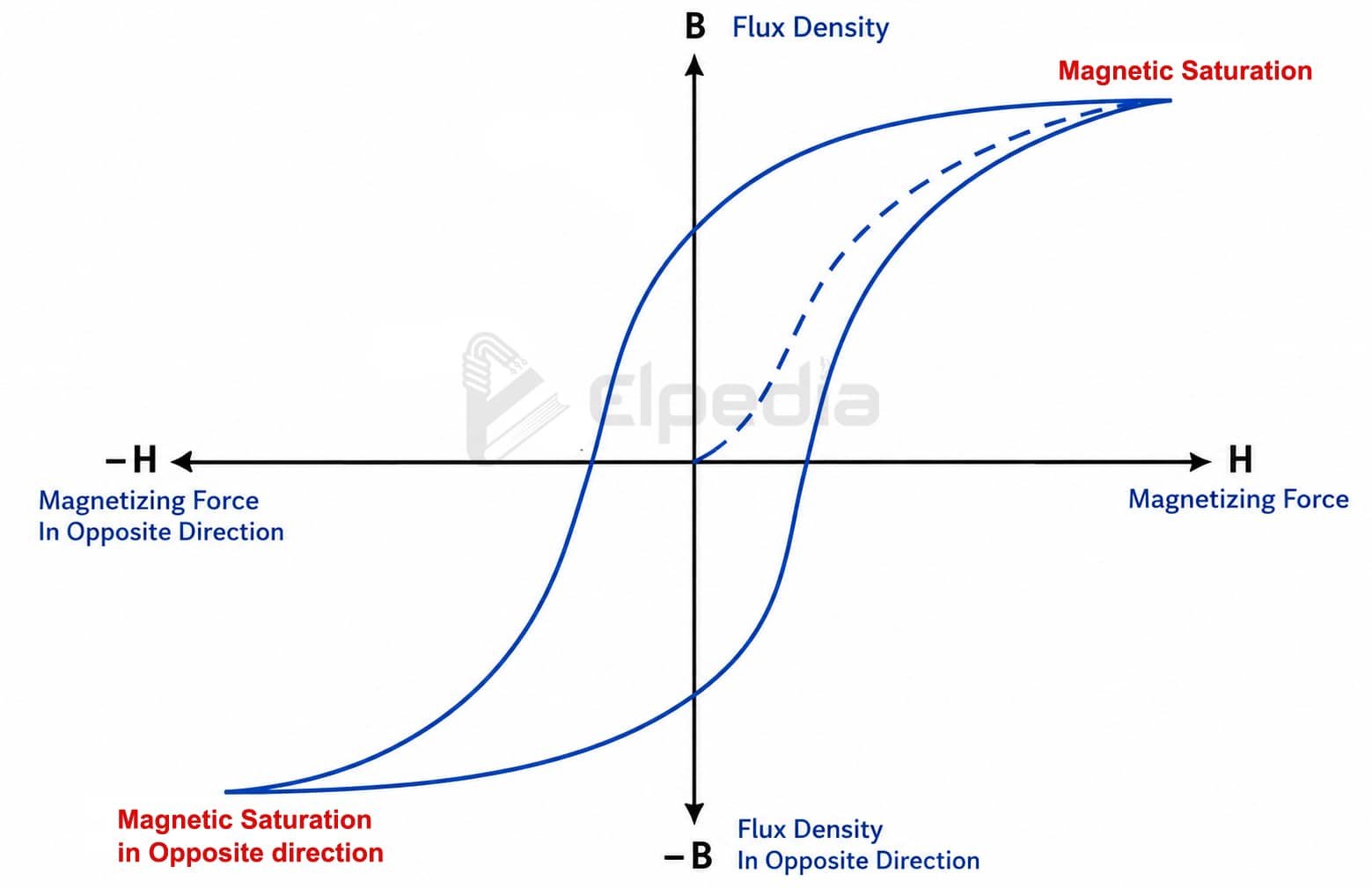
Ferromagnetic materials also exhibit magnetic hysteresis, in which the flux density (B) does not follow the same path when (H) is increased and decreased. In other words, the magnetic response depends partly on the previous magnetic state or magnetic history of the material.
Therefore, for ferromagnetic materials, permeability (μ) and relative permeability (μr) are generally not constant. Their values depend on the operating point, the material, and its magnetic history.
For practical design, particularly when a magnetic core operates close to saturation, engineers should use the actual B–H curves provided in the material manufacturer’s datasheet rather than assuming a constant permeability.
Magnetic Path, Air Gap, Leakage Flux, and Fringing
In practical magnetic circuits, magnetic flux does not always remain completely confined to the intended magnetic path. Some flux may escape through the surrounding air, and the flux lines spread outward when they cross an air gap.
These effects are important when analyzing and designing transformers, motors, generators, inductors, and other electromagnetic devices.
The magnetic path is the route followed by the main magnetic flux in a magnetic circuit. It usually passes through a ferromagnetic core, such as iron or steel, and may also include one or more air gaps.
The symbol ℓ represents the mean length of the magnetic path in magnetic-circuit calculations.
Ferromagnetic materials are commonly used for the core because they have high permeability and therefore provide a low-reluctance path for magnetic flux. The reluctance of a uniform section is expressed as,
Thus, a shorter magnetic path and a material with higher permeability result in lower reluctance.
An air gap is a deliberate non-magnetic section, usually consisting of air or free space, introduced into the magnetic path. Because air has a much lower permeability than ferromagnetic core materials, an air gap introduces a high reluctance into the magnetic circuit.
Air gaps are commonly used in DC machines, electric motors, generators, inductors, and loudspeakers. They can help control the magnetic field, establish the required magnetic force, and reduce the risk of core saturation.
Even a horseshoe magnet has an effective air gap between its two poles. The reluctance of an air gap is approximately:
![\[\mathcal{R}_g=\frac{\ell_g}{\mu_0A_g}\]](https://elpedia.com/wp-content/ql-cache/quicklatex.com-70892ddce12a8ea1f463edbeb79dfd8f_l3.png "Rendered by QuickLaTeX.com")
where ℓg is the air-gap length and Ag is the effective cross-sectional area of the gap. Because μr of air is approximately 1, even a relatively small air gap can contribute significantly to the total reluctance of a magnetic circuit.
Leakage flux is the portion of magnetic flux that does not follow the intended magnetic path through the core. Instead, it passes through the surrounding air or other unintended paths.
In practical magnetic devices, leakage flux cannot be completely eliminated. It is particularly important in transformers, motors, generators, and inductors, where it can reduce magnetic coupling and affect the performance of the device.
The total flux can be considered as consisting of useful flux and leakage flux. The leakage coefficient is often used to describe the effect of leakage flux.
Depending on the construction and operating conditions of a magnetic device, typical values may be around 1.15–1.25. This indicates that leakage can be a significant design consideration, although the exact amount varies considerably between devices.
Fringing is the spreading or bulging of magnetic flux lines around the edges of an air gap. When magnetic flux crosses an air gap, the flux lines do not remain perfectly parallel to the core boundaries. Instead, they spread outward into the surrounding space.
As a result, the effective cross-sectional area of the air gap becomes slightly larger than the physical core area. This generally reduces the effective reluctance of the air gap compared with a calculation that assumes a uniform flux distribution.
For approximate calculations, the effective gap area may be estimated by accounting for the spreading of the flux around the gap edges. The exact correction depends on the geometry and dimensions of the magnetic circuit.
Types of Magnetic Circuits
Magnetic circuits can be classified based on the arrangement of their magnetic paths and the materials used in their construction.
Analogy between Magnetic circuit and Electric Circuit
The analogy between a magnetic circuit and an electric circuit was developed so that engineers could solve magnetic problems using the same methods they already knew from DC circuit analysis. It is a mathematical analogy, not a full physical equivalence, but it remains one of the most powerful conceptual tools in basic electrical engineering.
| Magnetic Circuit | Electric Circuit |
| A closed path for a magnetic flux forms a magnetic circuit. | A closed path for an electric current form an electric circuit. |
| Magnetic flux does not flow in a magnetic circuit. | Electric current always flows in an electric circuit. |
| MMF is the cause for producing flux. | EMF is the cause for producing current. |
| Weber is the unit of flux. | Ampere is the unit of current. |
| |
| Reluctance opposes the flow of flux. | Resistance opposes the flow of current. |
| |
| |
| |
| |
| Magnetic flux lines flow from the North pole to the South pole. | Electric current flows from the positive to negative terminal. |
![\[ \text{Magnetic Flux, } \, \Phi = \frac{F}{\mathcal{R}}\]](https://elpedia.com/wp-content/ql-cache/quicklatex.com-6b9cec9eae468141f6f1e66531d5058d_l3.png "Rendered by QuickLaTeX.com")
![\[\text{Electric Current,} \, I= \frac{V}{R}\]](https://elpedia.com/wp-content/ql-cache/quicklatex.com-aef405525bfb1c70ed6f80a3e962d7ff_l3.png "Rendered by QuickLaTeX.com")
![\[\text{Reluctance}, \,\mathcal{R}= \frac{l}{\mu_0 \mu_r A}\]](https://elpedia.com/wp-content/ql-cache/quicklatex.com-350244a0c242bf285013e70864986355_l3.png "Rendered by QuickLaTeX.com")
![\[\text{Resistance, R}= \frac{\rho l}{A}\]](https://elpedia.com/wp-content/ql-cache/quicklatex.com-c8e6c9fa67e26bebff281544aa52bf01_l3.png "Rendered by QuickLaTeX.com")
![\[\text{Permeance}, \, \Lambda = \frac{1}{\mathcal{R}}\]](https://elpedia.com/wp-content/ql-cache/quicklatex.com-a506d5dad53737fd36cc28d6cdea1c90_l3.png "Rendered by QuickLaTeX.com")
![\[\text{Conductance,} \, \rho= \frac{1}{R}\]](https://elpedia.com/wp-content/ql-cache/quicklatex.com-a509cc23dedeb9c7711178b38d9d33a2_l3.png "Rendered by QuickLaTeX.com")
![\[ \text{Flux density, B} = \frac{\phi}{A}\]](https://elpedia.com/wp-content/ql-cache/quicklatex.com-b831e3768d329e34d4cbfbb333415034_l3.png "Rendered by QuickLaTeX.com")
![\[ \text{Current density, J} = \frac{I}{A}\]](https://elpedia.com/wp-content/ql-cache/quicklatex.com-5a468b631b861b36770bb9e3945d1d58_l3.png "Rendered by QuickLaTeX.com")
![\[ \text{Magnetic field intensity, H} = \frac{NI}{l}\]](https://elpedia.com/wp-content/ql-cache/quicklatex.com-63d6a4dec98eb9bf57936de09fcb82e4_l3.png "Rendered by QuickLaTeX.com")
![\[\text{Electric field intensity, E} = \frac{V}{d}\]](https://elpedia.com/wp-content/ql-cache/quicklatex.com-59c526b0275b10c556f135ed87b4d663_l3.png "Rendered by QuickLaTeX.com")
The fundamental laws used in magnetic-circuit analysis have strong analogies with the laws of electrical circuits. These analogies provide a convenient way to analyze magnetic circuits using concepts similar to voltage, current, resistance, and Kirchhoff’s laws.
Hopkinson’s law F = Φℜ is the magnetic equivalent of Ohm’s law V = IR. Magnetic circuits can also be analyzed using principles analogous to Kirchhoff’s Current Law (KCL) and Kirchhoff’s Voltage Law (KVL).
At a magnetic junction, the total flux entering the junction is equal to the total flux leaving it, just like Kirchhoff’s Current Law. And the sum of the MMF drops around a closed magnetic path is equal to the total applied MMF. This is analogous to Kirchhoff’s Voltage Law.
Consider a magnetic circuit consisting of two core sections and an air gap. The three sections can be represented by three reluctances connected in series. The same magnetic flux passes through each section. This is analogous to resistors connected in series in an electrical circuit, where the total resistance is the sum of the individual resistances.
When a magnetic circuit provides two or more parallel paths for flux, the total reluctance can be analyzed similarly to parallel electrical resistances. Thus, parallel magnetic paths are conveniently analyzed by adding their permeances, just as parallel electrical conductances are added.
Limitations of the Magnetic-Circuit Analogy
Although the electrical and magnetic circuit analogies are extremely useful, they are not exact physical equivalents.
Magnetic flux does not represent the literal flow of conserved electric charge. Similarly, magnetic reluctance does not dissipate energy in the same way that electrical resistance dissipates electrical energy as heat.
The magnetic-circuit approximation also becomes less accurate when dealing with dynamic, high-frequency, nonlinear, or strongly distributed electromagnetic systems, such as high-frequency power converters, high-speed electrical machines, and systems with significant eddy-current or electromagnetic-wave effects. In such cases, a direct analysis based on Maxwell’s equations may be required.
Importance of Magnetic Equivalent Circuits
The magnetic equivalent circuit (MEC) approach provides a practical method for relating the required magnetic flux and MMF to the physical dimensions and materials of a magnetic device.
It is widely used in the preliminary design of transformers, motors, generators, inductors, and other electrical machines, including determining the required number of winding turns and magnetizing current.
Summary of Key Formulas and Definitions
- Magnetic flux Φ (Wb): Φ = ∬ B · dS ≈ BA cos θ. The total magnetic field lines passing through a surface. Measured in webers. Φ is sometimes written as magnetic flux φ in older texts.
- Magnetic flux density B (T): B = Φ / A; also B = μH. Describes flux concentration per unit area.
- Magnetic field strength / intensity H (A/m): H = NI / ℓ (for a coil), and F = Hℓ. Represents the magnetizing force along the path.
- Magnetomotive force F (At): F = NI; Hopkinson’s law: F = Φℜ. Drives flux like EMF drives current.
- Reluctance ℜ (At/Wb): ℜ = ℓ / (μA) = ℓ / (μ₀ μᵣ A). Opposition to flux.
- Permeance Λ (Wb/A·t): Λ = 1 / ℜ = μA / ℓ. Ease of flux establishment.


Good