Kirchhoff’s Laws: KCL and KVL for Circuit Analysis
Key Takeaways
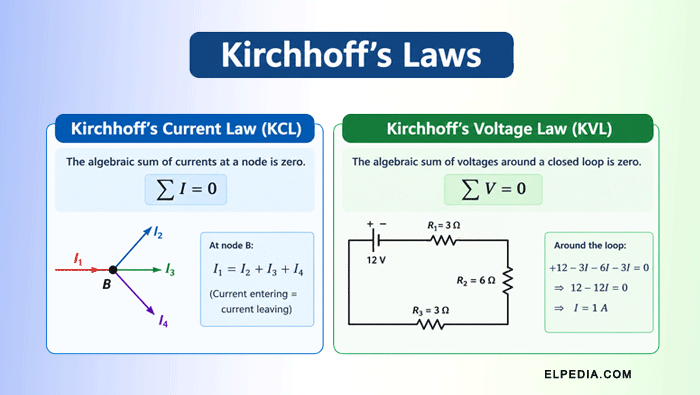
- Kirchhoff’s current law (KCL) is based on conservation of charge and states that the algebraic sum of currents at any node in an electrical circuit is zero.
- Kirchhoff’s voltage law (KVL) is based on conservation of energy and states that the algebraic sum of voltages around any closed circuit loop is zero.
- Applying Kirchhoff’s laws systematically allows you to solve for unknown branch currents and voltages in both DC circuits and low-frequency AC circuits, including complex circuits that cannot be reduced to simple series or parallel forms.
- This article walks through step-by-step solved problems using KCL and KVL, showing sign conventions, equation setup, and solution strategies Elpedia recommends for exam and real-world circuit analysis.
When you have a simple circuit with one battery and one resistor, Ohm’s law is usually enough to determine the relationship between voltage, current, and resistance.
But as a circuit becomes more complex—with multiple loops, voltage sources, and branches carrying currents in different directions—Ohm’s law alone is not enough.
You need a systematic method to determine how current flows through the different branches and how voltage is distributed across the circuit elements.
Gustav Kirchhoff, born on March 12, 1824, in Königsberg, Prussia, formulated his two circuit laws in 1845. These laws are known as Kirchhoff’s Current Law (KCL) and Kirchhoff’s Voltage Law (KVL).
They remain fundamental tools in electrical engineering for analyzing and designing electrical circuits.
Kirchhoff also made important contributions to physics, particularly in spectroscopy, and was the first to experimentally investigate the speed of electrical signals in wires.
Before studying Kirchhoff’s laws, it is useful to understand a few basic circuit terms.
- A node is a point in a circuit where two or more circuit elements are connected. When three or more branches meet at a node, it is commonly called a junction.
- A branch is a portion of a circuit between two nodes that contains one or more circuit elements carrying the same current.
- A loop is any closed path in a circuit that begins and ends at the same node without passing through any node more than once along the path.
- A closed circuit is a complete conducting path through which electric current can flow from a source and return to the source.
Consider a circuit containing a battery and three resistors connected through several branches.
To determine the current flowing through each resistor and the voltage across the different circuit elements, we can apply Kirchhoff’s Current Law at the nodes and Kirchhoff’s Voltage Law around the loops.
These two laws provide a systematic approach for analyzing circuits that are too complex to solve using Ohm’s law alone.
Physical Foundations: Conservation of Charge and Energy
Kirchhoff’s two laws are based on two fundamental conservation principles in physics: Kirchhoff’s Current Law (KCL) is based on the conservation of electric charge and Kirchhoff’s Voltage Law (KVL) is based on the conservation of energy.
Why does current entering a node have to equal current leaving it?
Electric charge cannot be created or destroyed. In a normal copper wire under steady-state conditions, charge does not continuously accumulate at a node.
If more charge were entering a node than leaving it, the charge at that point would increase and produce an electric field that would drive charge away.
Therefore, the total current entering a node must equal the total current leaving it. This is the physical basis of Kirchhoff’s Current Law.
KVL is based on the law of conservation of energy. When a charge moves around a closed circuit, the net change in its electrical energy after returning to its starting point must be zero.
A voltage source, such as a battery, supplies energy to the charge. As the charge passes through resistors and other circuit elements, electrical energy is transferred to other forms, such as heat or mechanical energy.
Because energy is conserved, the total voltage rise provided by the sources must equal the total voltage drop across the circuit elements around a closed loop.
Therefore, the algebraic sum of all voltage rises and voltage drops around any closed loop is zero. This is the physical basis of Kirchhoff’s Voltage Law.
The usual circuit-analysis form of Kirchhoff’s laws is based on the lumped-element model.
In this model, circuit elements are treated as discrete components, while connecting wires are ideal conductors, and the operating frequency is low enough that electromagnetic wave effects along the wires can be neglected.
Kirchhoff’s Current Law (KCL): Statement and Notation
Kirchhoff’s Current Law (KCL) states that the algebraic sum of all currents at any node in a circuit is zero. Equivalently, the total current entering a node is equal to the total current leaving it. Kirchhoff’s current law is also known as the junction rule.
Mathematically, KCL can be expressed as,
![\[ \sum I_{\text{in}} = \sum I_{\text{out}} \]](https://elpedia.com/wp-content/ql-cache/quicklatex.com-e96b2c61b5156001a51345ed8db98029_l3.png "Rendered by QuickLaTeX.com")
or, using an algebraic sign convention,
![\[\sum I_k = 0\]](https://elpedia.com/wp-content/ql-cache/quicklatex.com-216109c1050effb17d4601e1cfeda0e4_l3.png "Rendered by QuickLaTeX.com")
where Ik represents the current in each branch connected to the node.
A current entering the node may be assigned a positive sign and a current leaving the node a negative sign, or vice versa. The choice does not matter as long as the same convention is used consistently.
A node is a point or continuous conducting region in a circuit where two or more circuit elements are electrically connected.
When applying KCL, you assign a reference direction to each unknown branch current using arrows. These directions are assumed directions and do not need to be correct initially.
If the calculated current is positive, the actual current flows in the assumed direction. If the calculated current is negative, the actual current flows in the direction opposite to the assumed arrow.
Thus, the assumed current direction is simply a reference used to formulate the circuit equations.
Understanding Branch Currents and Nodes
Consider a node where three branches are connected. Suppose current (I1) enters the node, current (I2) enters the node, and current (I3) leaves the node.
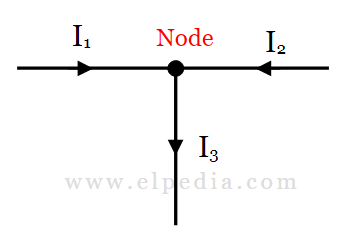
Taking currents entering the node as positive and currents leaving as negative, KCL gives,
![\[I_1 + I_2 - I_3 = 0\]](https://elpedia.com/wp-content/ql-cache/quicklatex.com-4290cf33cd02d08ccbdd40632ce87dcd_l3.png "Rendered by QuickLaTeX.com")
![\[\text{Therefore, }I_3 = I_1 + I_2\]](https://elpedia.com/wp-content/ql-cache/quicklatex.com-599bfd069a8c0cea92a1935dda1a841a_l3.png "Rendered by QuickLaTeX.com")
This means that the total current entering the node must equal the total current leaving it.
For example, suppose I1 = 3 A and I2 = 2 A, with both currents entering the node. Then:
![\[I_3 = 3 + 2 = 5\text{ A} \]](https://elpedia.com/wp-content/ql-cache/quicklatex.com-40b310667799fc660a9064feb27cf6c0_l3.png "Rendered by QuickLaTeX.com")
Thus, 5 A flows out of the node. Now suppose you initially assumed that I3 also enters the node. Using the same sign convention, the KCL equation becomes,
![\[I_1 + I_2 + I_3 = 0 \]](https://elpedia.com/wp-content/ql-cache/quicklatex.com-9f5bc51ad0ac4782ac2e374b15bdea95_l3.png "Rendered by QuickLaTeX.com")
Substituting I1 = 3 A and I2 = 2 A,
![\[ 3 + 2 + I_3 = 0 \]](https://elpedia.com/wp-content/ql-cache/quicklatex.com-6286324f513f2ce76727d5ec491ac320_l3.png "Rendered by QuickLaTeX.com")
![\[\text{Therefore, } I_3 = -5 \text{ A} \]](https://elpedia.com/wp-content/ql-cache/quicklatex.com-0d65e7efdfd65b284cbc826e28e48040_l3.png "Rendered by QuickLaTeX.com")
The negative sign indicates that the actual current flows in the direction opposite to the assumed direction.
A negative current is therefore not an error; it provides information about the actual direction of current flow.
This principle applies regardless of the number of branches connected to a node.
Whether a node has three, five, or ten connected branches, the total current entering the node must equal the total current leaving it.
Solved Examples for KCL
Elpedia emphasizes solved problems for mastery. Let’s work through several DC examples using KCL.
Solved Problem 1
A node has five branch currents. Currents I₁ = 3 A and I₂ = 2 A enter the node. I₃ = 1 A enters the node, while I₄ = 4 A leaves the node. Find the value and direction of I₅.
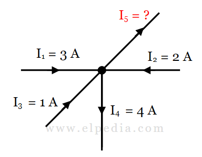
Solution : Using Kirchhoff’s Current Law (KCL):
![\[\sum I_{\text{entering}} = \sum I_{\text{leaving}} \]](https://elpedia.com/wp-content/ql-cache/quicklatex.com-8b4c2d5df2cc2db8f94a63d35a028a06_l3.png "Rendered by QuickLaTeX.com")
Therefore,
![\[\text{Therefore, } 3 + 2 + 1 = 4 + I_5 \]](https://elpedia.com/wp-content/ql-cache/quicklatex.com-5b288bf85a1f810dcab0ae9df8bd2eaa_l3.png "Rendered by QuickLaTeX.com")
![\[6 = 4 + I_5 \]](https://elpedia.com/wp-content/ql-cache/quicklatex.com-f873a480484d44a6d6cf62aecee09ca2_l3.png "Rendered by QuickLaTeX.com")
![\[I_5 = 2\text{ A} \]](https://elpedia.com/wp-content/ql-cache/quicklatex.com-df0f91b1ea25f3dcd8198ae0c0f2f0dd_l3.png "Rendered by QuickLaTeX.com")
Therefore, I₅ = 2 A leaving the node.
Solved Problem 2
A 24 V DC source is connected to three parallel resistors: R₁ = 4 Ω, R₂ = 6 Ω and R₃ = 12 Ω. Find the total current supplied by the source.
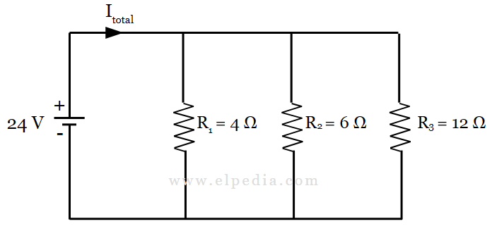
Solution : Since the resistors are connected in parallel, the voltage across each resistor is the same, 24 V.
Using Ohm’s law,
![\[I = \frac{V}{R} \]](https://elpedia.com/wp-content/ql-cache/quicklatex.com-5e5b06538c172b0c28e482f12edaad3d_l3.png "Rendered by QuickLaTeX.com")
the current through each branch is calculated as follows.
For R₁ = 4 Ω,
![\[I_1 = \frac{24}{4} = 6\text{ A}\]](https://elpedia.com/wp-content/ql-cache/quicklatex.com-c5d6a45a8de2618fa87643b9624507ea_l3.png "Rendered by QuickLaTeX.com")
For R₂ = 6 Ω,
![\[I_2 = \frac{24}{6} = 4\text{ A}\]](https://elpedia.com/wp-content/ql-cache/quicklatex.com-737bb39345399891ec0ef78929c53ad5_l3.png "Rendered by QuickLaTeX.com")
For R₃ = 12 Ω,
![\[I_3 = \frac{24}{12} = 2\text{ A}\]](https://elpedia.com/wp-content/ql-cache/quicklatex.com-f21463340f260850c41bed934bda336d_l3.png "Rendered by QuickLaTeX.com")
At the node where the current splits into the three parallel branches, Kirchhoff’s Current Law states that the total current entering the node equals the total current leaving it:
![\[I_{\text{total}} = I_1 + I_2 + I_3\]](https://elpedia.com/wp-content/ql-cache/quicklatex.com-9e72ec996233716a2e927a4a5e938bca_l3.png "Rendered by QuickLaTeX.com")
Substituting the branch currents,
![\[I_{\text{total}} = 6 + 4 + 2 = 12\text{ A}\]](https://elpedia.com/wp-content/ql-cache/quicklatex.com-c43b0023f78d56905b3254f8138dc0ce_l3.png "Rendered by QuickLaTeX.com")
Therefore, the source supplies a total current of 12 A.
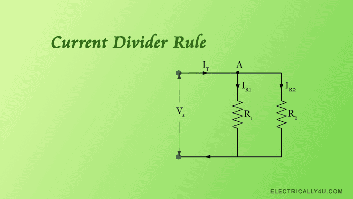
For more information on how current divides between parallel branches, see the Current Divider Rule.
Solved Problem 3
For the circuit shown below, find the voltage across 10 Ω resistor and current passing through it.
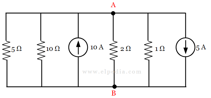
Solution : The given circuit is a parallel circuit, and consists of a single node A. By assuming voltage V at the node A w.r.t. B, we can find out the current in the 10 Ω branch. The given circuit is redrawn by assuming the current direction.
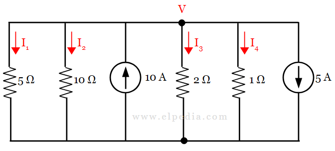
Applying KCL at node V,
![\[I_1 + I_2 + I_3 + I_4 + 5 = 10 --->(1) \]](https://elpedia.com/wp-content/ql-cache/quicklatex.com-b4fe37dc619ab7102cacb4a218e8b298_l3.png "Rendered by QuickLaTeX.com")
By using Ohm’s law, the branch currents are written as,
![\[I_1 = \frac{V}{5},\, I_2 = \frac{V}{10}, \, I_3 = \frac{V}{2}, \, I_4 = \frac{V}{1} \]](https://elpedia.com/wp-content/ql-cache/quicklatex.com-eb0bfea95c4c3995b284f914cf017454_l3.png "Rendered by QuickLaTeX.com")
Equation(1) gives,
![\[\frac{V}{5}+ \frac{V}{10}+ \frac{V}{2}+ \frac{V}{1} +5 = 10 \]](https://elpedia.com/wp-content/ql-cache/quicklatex.com-68831f31c821a588784c106d9f76aa84_l3.png "Rendered by QuickLaTeX.com")
![\[V\left[\frac{1}{5}+ \frac{1}{10}+ \frac{1}{2}+ \frac{1}{1}\right] = 10 - 5 \]](https://elpedia.com/wp-content/ql-cache/quicklatex.com-81e27df5777fccde1824ab37ffbed9d9_l3.png "Rendered by QuickLaTeX.com")
![\[V\left[0.2 + 0.1 + 0.5 + 1 \right] = 5\]](https://elpedia.com/wp-content/ql-cache/quicklatex.com-2bc29c66df8f736329cbd6516d64bc8a_l3.png "Rendered by QuickLaTeX.com")
![\[V = \frac{5}{1.8} \]](https://elpedia.com/wp-content/ql-cache/quicklatex.com-75a3267a8ba3021aaf92606e16f37d5a_l3.png "Rendered by QuickLaTeX.com")
![\[V = 2.78 \,V \]](https://elpedia.com/wp-content/ql-cache/quicklatex.com-c379fe071c5b86412184fdecc8dd1d7f_l3.png "Rendered by QuickLaTeX.com")
The obtained value is the voltage across the 10 Ω resistor. Thus the current passing through it is,
![\[I = \frac{V}{R} = \frac{2.78}{10} \]](https://elpedia.com/wp-content/ql-cache/quicklatex.com-a782d3173edf500b86debae73318020d_l3.png "Rendered by QuickLaTeX.com")
![\[I = 0.278 \, A \]](https://elpedia.com/wp-content/ql-cache/quicklatex.com-525a72d1af9ef2d0cd4aba8c9dac8f63_l3.png "Rendered by QuickLaTeX.com")
Kirchhoff’s Voltage Law (KVL): Statement and Loop Concepts
Kirchhoff’s Voltage Law (KVL) states that the algebraic sum of all voltages around any closed loop in a circuit is zero. In other words, the total voltage rises around a closed loop must equal the total voltage drops.
Mathematically, KVL is expressed as:
![\[\sum V = 0\]](https://elpedia.com/wp-content/ql-cache/quicklatex.com-e4f9cccd48ee36aa3ffa2369e69af1ba_l3.png "Rendered by QuickLaTeX.com")
This law is a direct application of the principle of conservation of energy to an electrical circuit.
A loop is any closed path in a circuit that starts and ends at the same node without passing through any node more than once.
A mesh is a loop that does not contain any other loop within it. A loop can contain any combination of voltage sources and circuit elements such as resistors, capacitors, and inductors.
When applying KVL, each voltage is assigned a sign according to the chosen traversal direction.
For example, when traversing an ideal voltage source from its negative terminal to its positive terminal, there is a voltage rise, represented as (+V). Traversing from the positive terminal to the negative terminal gives a voltage drop, represented as (-V).
For a resistor, if you traverse it in the same direction as the assumed current, the voltage change is a drop, represented as (-IR). If you traverse it opposite to the assumed current direction, the voltage change is a rise, represented as (+IR).
The important point is to choose a consistent sign convention and traversal direction throughout the loop. The final result is unchanged regardless of the direction chosen.
Kirchhoff’s voltage law equation applies in both DC circuits and low-frequency AC circuits. However, at very high frequency, time-varying magnetic fields can violate the simple loop rule, as we’ll discuss later.
Procedure for Applying KVL Around a Loop
The following steps provide a systematic procedure for applying Kirchhoff’s Voltage Law (KVL) during circuit analysis:
- Choose a loop and traversing direction. Select a closed loop to analyze and choose a direction in which to traverse it, either clockwise or counterclockwise. Either direction is valid, provided you follow it consistently while writing the KVL equation.
- Assign current directions and polarities. For each resistor, mark its positive and negative voltage terminals according to the assumed current direction. The terminal where the assumed current enters the resistor is taken as positive, and the terminal where it leaves is taken as negative.
- Walk around the loop and write voltages. Starting at any node, move around the loop. Write +V for every voltage rise and −V for every voltage drop you encounter. The resulting KVL equation will be ∑Vₙ = 0.
- Substitute Ohm’s law and solve. Replace each resistor voltage drop with IR (using Ohm’s law). Combine these KVL equations with any KCL equations to form simultaneous equations and solve for unknown currents and voltages.
Solved Examples for KVL
This section serves as a focused problem-solving on KVL. Let’s work through these problems for clear understanding.
Solved Problem 4
Find the unknown voltage drop in the circuit given below, which is supplied by 100 V source.
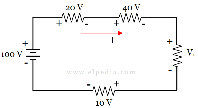
Solution : In the given problem, the current directions and polarities are already assigned.
According to Kirchhoff’s voltage law, the sum of voltage rise is equal to the sum of voltage drops. Therefore, let’s write the KVL equation, traversing in the current direction.
![\[100 = 20 + 40 + V_1 + 10 \]](https://elpedia.com/wp-content/ql-cache/quicklatex.com-0843ff73243498604584047a87ff1d0d_l3.png "Rendered by QuickLaTeX.com")
![\[V_1 = 100-70 \]](https://elpedia.com/wp-content/ql-cache/quicklatex.com-46e930b80696c45221f5512977f25694_l3.png "Rendered by QuickLaTeX.com")
![\[V_1 = 30 \, V \]](https://elpedia.com/wp-content/ql-cache/quicklatex.com-e6eda978ea57352af8d7cb5ccc2e821a_l3.png "Rendered by QuickLaTeX.com")
Solved Problem 5
Consider a closed circuit with a 24 V DC source and three resistors connected in series: R₁ = 200 Ω, R₂ = 400 Ω and R₃ = 600 Ω. Find the loop current and voltage drop across the resistors.
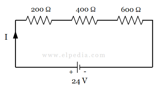
Solution : Let us assign the polarities to the given circuit and redraw the circuit as shown below.
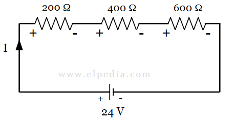
Since the resistors are connected in series, their resistances are added.
![\[R_{\text{total}} = R_1 + R_2 + R_3 \]](https://elpedia.com/wp-content/ql-cache/quicklatex.com-8b4dd5984511c72c2cb6958a380a18b9_l3.png "Rendered by QuickLaTeX.com")
![\[R_{\text{total}} = 200 + 400 + 600 = 1200 \,\Omega\]](https://elpedia.com/wp-content/ql-cache/quicklatex.com-a965ab8677857a7588c24418b9a84b2c_l3.png "Rendered by QuickLaTeX.com")
Using Ohm’s law,
![\[I = \frac{V}{R_{\text{total}}} \]](https://elpedia.com/wp-content/ql-cache/quicklatex.com-49741dd90290c2e4716ad74e31c0b22c_l3.png "Rendered by QuickLaTeX.com")
![\[ I = \frac{24}{1200} = 0.02\text{ A} \]](https://elpedia.com/wp-content/ql-cache/quicklatex.com-0b7feaa682b7573d10a1e656767cab10_l3.png "Rendered by QuickLaTeX.com")
Therefore, the current flowing through all three series resistors is 0.02 A.
The voltage drop across a resistor is given by,
![\[ V_R = IR \]](https://elpedia.com/wp-content/ql-cache/quicklatex.com-865fb391008200abfabbc5a45e81bc85_l3.png "Rendered by QuickLaTeX.com")
For R₁ = 200 Ω,
![\[V_1 = 0.02 \times 200 = 4\text{ V} \]](https://elpedia.com/wp-content/ql-cache/quicklatex.com-3bb3c81d8310c91033bffd33f62ff3e9_l3.png "Rendered by QuickLaTeX.com")
For R₂ = 400 Ω,
![\[ V_2 = 0.02 \times 400 = 8\text{ V} \]](https://elpedia.com/wp-content/ql-cache/quicklatex.com-3524888b98f84f63fbbd2e4381e3e91b_l3.png "Rendered by QuickLaTeX.com")
For R₃ = 600 Ω,
![\[V_3 = 0.02 \times 600 = 12\text{ V} \]](https://elpedia.com/wp-content/ql-cache/quicklatex.com-40d69c0fc2b1682fa9e5203b41f14af4_l3.png "Rendered by QuickLaTeX.com")
Now, write the Kirchhoff’s voltage law equation around the loop,
![\[ +24 - 4 - 8 - 12 = 0 \]](https://elpedia.com/wp-content/ql-cache/quicklatex.com-7d30829745eede2c1959676d7e4929e1_l3.png "Rendered by QuickLaTeX.com")
The sum of all the voltages around the loop equals zero. The energy supplied by the battery to each coulomb of charge exactly equals the energy dissipated across the three resistors. The same KVL principle can be extended to more complex circuits containing multiple loops.
Solved Problem 6
Consider the following circuit with two voltage sources and three resistors. Find the current I and voltage drop across 10 Ω resistor.
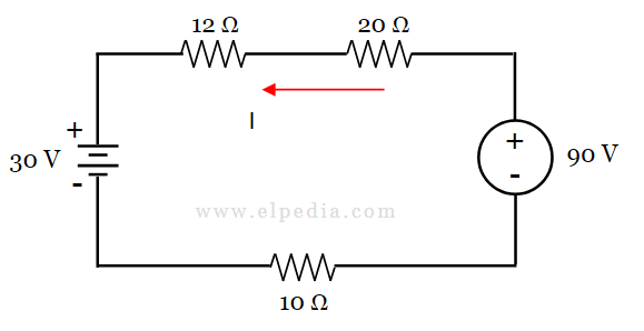
Solution : The given circuit is redrawn by assigning the polarities by traversing in the direction of current.
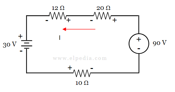
By using Ohm’s law, the voltage across each resistors are determined as follows.
![\[V = I\times R \]](https://elpedia.com/wp-content/ql-cache/quicklatex.com-b40ec19ec43473548803ccd408776e67_l3.png "Rendered by QuickLaTeX.com")
![\[\text{Voltage across 12 ohm resistor} = 12I --->(1)\]](https://elpedia.com/wp-content/ql-cache/quicklatex.com-8f0a3754631a473f7de8ead087e8b957_l3.png "Rendered by QuickLaTeX.com")
![\[\text{Voltage across 20 ohm resistor} = 20I --->(2) \]](https://elpedia.com/wp-content/ql-cache/quicklatex.com-a56cbd8f149509f6dba6c5f93b2dc82f_l3.png "Rendered by QuickLaTeX.com")
![\[\text{Voltage across 10 ohm resistor} = 10I --->(3)\]](https://elpedia.com/wp-content/ql-cache/quicklatex.com-eca769eeb53c713eef5af60d9e910b5b_l3.png "Rendered by QuickLaTeX.com")
Now let’s apply KVL to the loop traversing in the current direction. By KVL, the sum of voltage rise is equal to the sum of voltage drops. Therefore,
![\[90 = 20I +12I + 30+ 10I \]](https://elpedia.com/wp-content/ql-cache/quicklatex.com-705c2e2866fbce51b7f9618e3946297b_l3.png "Rendered by QuickLaTeX.com")
![\[42I = 90-30 \]](https://elpedia.com/wp-content/ql-cache/quicklatex.com-7d77284df26c2fc4c87b73104a72425c_l3.png "Rendered by QuickLaTeX.com")
![\[I = \frac{60}{42} \]](https://elpedia.com/wp-content/ql-cache/quicklatex.com-204803fb906bfdb103e863cb29541fd3_l3.png "Rendered by QuickLaTeX.com")
![\[I = 1.428 \, A\]](https://elpedia.com/wp-content/ql-cache/quicklatex.com-9db8c17caef51e824c3d67f931abdec3_l3.png "Rendered by QuickLaTeX.com")
Voltage drop across 10 Ω resistor is determined from equation(3) as,
![\[ V = 10 \times 1.428 \]](https://elpedia.com/wp-content/ql-cache/quicklatex.com-fd63d70274002a985824c438d9a5cd26_l3.png "Rendered by QuickLaTeX.com")
![\[V = 14.28 \, V \]](https://elpedia.com/wp-content/ql-cache/quicklatex.com-72a7bdab1a5cac49c545ad39bde69ce0_l3.png "Rendered by QuickLaTeX.com")
Combining KCL and KVL for Circuit Analysis
Kirchhoff’s Current Law (KCL) and Kirchhoff’s Voltage Law (KVL) can be used together to analyze complex electrical circuits that cannot be reduced to simple series or parallel combinations.
By applying KCL at nodes and KVL around loops, circuit analysis can be formulated as a set of equations whose unknowns are branch currents, node voltages, or loop currents.
Nodal analysis uses KCL as its fundamental principle. First, one node is selected as the reference node (ground), and the voltages of the remaining nodes are defined with respect to this reference. KCL is then applied at each non-reference node.
The current through each branch is expressed in terms of the voltage difference between the connected nodes using element relationships such as Ohm’s law. The resulting equations can then be solved for the unknown node voltages.
Mesh analysis uses KVL as its fundamental principle. A mesh current is assigned to each independent mesh, and KVL is applied around each mesh. The voltage drops across resistors are expressed in terms of the mesh currents using Ohm’s law.
The resulting equations form a system of simultaneous equations that can be solved to determine the unknown mesh currents.
Both nodal and mesh analysis convert a circuit into a system of equations that can be solved systematically. Modern tools like SPICE automate this process, but for exams and deeper understanding, you need to be able to set up these equations by hand.
For circuits where multiple independent sources interact, the Superposition Theorem offers yet another powerful approach.
Applying Kirchhoff’s Laws to DC and AC Circuits
In a steady-state DC circuit, voltage and current values are constant with time. Kirchhoff’s laws therefore lead to algebraic equations that can be solved directly for the unknown currents and voltages.
For sinusoidal AC circuits under the lumped-element approximation, Kirchhoff’s laws are applied in the same fundamental way.
However, instead of using only resistance, circuit elements are represented by their complex impedances, and voltages and currents are represented by phasors.
The impedances of the basic passive elements are ZR = R, ZL = jωL and ZC = 1/(jωC).
For a series AC circuit, KVL can be written in phasor form as:
![\[\tilde{V}_\text{source} = \tilde{I}Z_1+\tilde{I}Z_2+\cdots+\tilde{I}Z_n \]](https://elpedia.com/wp-content/ql-cache/quicklatex.com-b0809035ffe21e6f4bcb017b8b6732cb_l3.png "Rendered by QuickLaTeX.com")
Consider a series RL circuit with a total impedance of Z = 30 + j40 Ω driven by 100∠0° V source.
The magnitude of the impedance is
![\[ |Z| = \sqrt{30^2+40^2}=50 \,\Omega \]](https://elpedia.com/wp-content/ql-cache/quicklatex.com-372053a42c0b51bf85126119b7e0eacd_l3.png "Rendered by QuickLaTeX.com")
The current through the circuit is given by,
![\[ I = \frac{100\angle0^\circ}{50\angle53.13^\circ} \]](https://elpedia.com/wp-content/ql-cache/quicklatex.com-61d4020cd41a568a4135caba26ad38b4_l3.png "Rendered by QuickLaTeX.com")
![\[I =2\angle-53.13^\circ \text{ A} \]](https://elpedia.com/wp-content/ql-cache/quicklatex.com-bef56816e49223d74b112e9670ee7676_l3.png "Rendered by QuickLaTeX.com")
The voltage drops across the resistor and inductor are phasor quantities. Their vector sum is equal to the source voltage, satisfying KVL.
For more information on phasors and their addition, see Phasor Diagram and Phasor Addition.
At very high frequencies, the lumped-element model breaks down. In high frequency AC circuits, wires behave as transmission lines with distributed inductance and capacitance.
Kirchhoff’s laws still work in the low frequency limit but require augmentation or replacement by full Maxwell’s equations at microwave and optical frequencies.
Analyzing a Complex Circuit with Multiple Branch Currents
In more realistic example circuits, such as a Wheatstone bridge with five or six resistors, you’ll encounter three or more nodes and multiple loops. The key is to select a sufficient set of independent equations.
For a connected circuit with (N) nodes, only (N-1) independent KCL equations are required. The remaining node equation is dependent on the others and would therefore be redundant.
For a planar circuit, KVL can be applied around each independent mesh. The number of independent meshes in a connected network is M = B – N + 1, where (B) is the number of branches and (N) is the number of nodes.
Here’s how to approach it systematically:
- Label all nodes (A, B, C, …) and assign reference directions to the unknown branch currents.
- Write KCL at (N − 1) nodes.
- Write KVL around each independent mesh, substituting V = IR for resistors.
- Solve the resulting system of simultaneous equations.
After solving the equations, verify the results by checking KCL at the remaining node that was not used to form an independent equation. The calculated currents should satisfy KCL at that node as well.
You can also verify KVL around other closed loops. If KVL is satisfied for a complete set of independent meshes, KVL will also be satisfied for other loops formed from those meshes.
For a DC circuit containing only resistors and independent sources, another useful check is power conservation:
![\[P_{\text{delivered}}=P_{\text{dissipated}}\]](https://elpedia.com/wp-content/ql-cache/quicklatex.com-8ce5c23f11d58c0791634773aa339009_l3.png "Rendered by QuickLaTeX.com")
Thus, the total power supplied by the sources should equal the total power dissipated by the resistors, apart from small differences caused by rounding.
For circuits that can be simplified using source transformations or star-delta conversions, those techniques can reduce the number of equations needed.
Common Mistakes and Practical Tips When Applying Kirchhoff’s Laws
Frequent errors to avoid:
- Mislabeling the direction of electric current and then forgetting to account for the negative sign in your answer.
- Mixing voltage rises and drops within the same loop equation (e.g., adding a drop as a rise).
- Writing KCL at all N nodes instead of (N − 1), then wondering why your system is underdetermined.
- Confusing the potential difference across a source with the potential difference across a resistor.
Elpedia’s checklist for start analyzing circuits:
- Draw the circuit diagram with clear labels for all nodes, branches, and assumed current directions.
- Mark polarity (+ and −) across every element based on assumed current direction.
- Write KCL at your chosen (N − 1) nodes.
- Write KVL around your chosen independent loops.
- Substitute component relations (V = IR or impedance for AC).
- Solve the simultaneous equations.
- Interpret any negative value as a reversal of assumed direction, not as an error.