Electrical Engineering Basics: Core Concepts, Circuits, and Practical Skills
Electrical engineering is the study, design, and application of systems that generate, transmit, control, and convert electricity, electronics, and electromagnetic energy. An electrical engineer must understand fundamental electrical quantities and basic laws of circuit analysis to do useful work in any sub-discipline.
On a typical day, electrical engineers work on tasks ranging from designing power systems and selecting electrical components to programming controllers, testing electronic devices, and verifying that installations meet safety codes.
Some focus exclusively on power generation and transmission; others design control systems for industrial machinery or build digital integrated circuits for consumer electronics.
This article covers basic electrical engineering from the ground up: electric charge, current, voltage, resistance, Ohm’s law, electrical circuits, AC circuits, electrical machines, and the practical skills you need to move from theory to working hardware.
What you will learn:
- How electric charge, current, voltage, and resistance relate to each other
- The difference between DC and AC, and why it matters for power and electronics
- How to analyze series, parallel, and mixed circuits using Kirchhoff’s laws
- What phasors, impedance, and power factor mean in AC circuits
- Core electrical components, machines, measurement tools, and safety practices
- Pathways to building a career in electrical engineering
Electric Charge and the Nature of Electricity
Electricity is the flow of electric charge. Electric charge is a fundamental property of matter carried by subatomic particles: protons carry positive charge, electrons carry negative charge. The magnitude of a single electron’s charge is 1.602 × 10⁻¹⁹ coulombs (C), the elementary charge. One coulomb equals the charge transported by one ampere of current in one second.
In everyday circuits, charges are tiny fractions of a coulomb moving each second. By contrast, a single lightning bolt can transfer tens of coulombs in a flash. That difference in scale is worth remembering: the same physics governs a microcontroller and a thunderstorm, but the numbers differ by many orders of magnitude.
Static electricity refers to charges at rest on surfaces. Rubbing a balloon on hair separates charges, causing hair to stand up. Current electricity refers to charges moving through conductors in a circuit, like power flowing through a home’s wires to a light.
Coulomb’s Law describes the force between two point charges: the force is proportional to the product of the charge magnitudes and inversely proportional to the square of the distance between them. Two hypothetical 1 C charges separated by 1 meter would exert a force of about 8.99 × 10⁹ newtons on each other.
In real circuits, charges are far smaller, so electrostatic forces between individual charges are negligible compared to the collective flow of electrons. At a deeper level, Maxwell’s Equations explain how electric and magnetic fields interact, but for circuit analysis, Coulomb’s Law and the concept of charge are the starting points.
Current, Voltage, and Resistance: Core Concepts
Electric current (symbol I) is the rate of flow of electric charge: I = Q / t. Current is measured in amperes (A), where 1 A equals 1 coulomb per second. A household light bulb might draw 0.5 A; a car starter motor can pull 200 A or more.
Voltage, also called electrical potential difference, is the energy per unit charge that drives current between two points in a circuit. Voltage is measured in volts (V). A 12 V battery provides 12 joules of energy for every coulomb of charge it pushes through the circuit. Without voltage, current does not flow; it is the “push” behind the current flow.
Resistance is the opposition to current flow through a material, measured in ohms (Ω), expressed as R = ρ × ℓ / A. Resistance depends on the material’s resistivity (ρ), the conductor’s length (ℓ), and its cross-sectional area (A).
Materials like copper and aluminum have low resistance and serve as conductors. Materials like PVC and glass have high resistance and serve as insulators. Discrete resistors are components placed in circuits to set specific resistance values.
A common analogy compares voltage to water pressure, current to flow rate, and resistance to a narrow pipe. The analogy is useful for intuition, but the physical definitions and units matter more: current in amperes, voltage in volts, resistance in ohms.
Ohm’s Law and Basic Circuit Relationships
Ohm’s Law states V = I × R. Rearranged, I = V / R and R = V / I. This single relationship connects voltage, current, and resistance in a circuit.
A 12 V battery connected to a 6 Ω resistor produces a current of I = 12 / 6 = 2 A. If 5 A flows through a 4 Ω resistor, the voltage drop across it is V = 5 × 4 = 20 V. These calculations are the bread and butter of circuit work.
In DC circuits, Ohm’s Law applies directly. In AC circuits, resistance extends to impedance (which includes effects of capacitors and inductors), but the same form V = I × Z holds for RMS values. Understanding the basics of Ohm’s law first makes the AC extension straightforward.
Practical uses include sizing resistors so that current stays within a device’s safe rating, verifying that voltage drops in a series chain add to the source voltage, and interpreting readings on a multimeter. If you measure 9 V across a resistor and know its value is 3 Ω, you can confirm 3 A of current without breaking the circuit to insert an ammeter.
Direct Current (DC) vs Alternating Current (AC)
AC (alternating current) is a reversing flow: voltage and current change direction periodically, following a sinusoidal waveform. DC (direct current) has a constant flow in one direction. This distinction shapes how power reaches your home and how electronics run inside your devices.
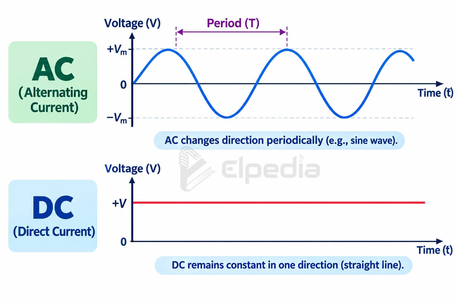
DC sources include batteries, solar cells, and DC power supplies. DC loads include electronics, LED drivers, and digital logic circuits where stable, unidirectional current is required.
AC is the standard for mains electricity worldwide. North American outlets supply 120 V RMS at 60 Hz. Most of Europe and Asia use 230 V at 50 Hz. Single-phase systems are common in residential applications, powering lights and appliances. Three-phase systems are used for industrial power due to their higher efficiency and ability to drive large induction motors.
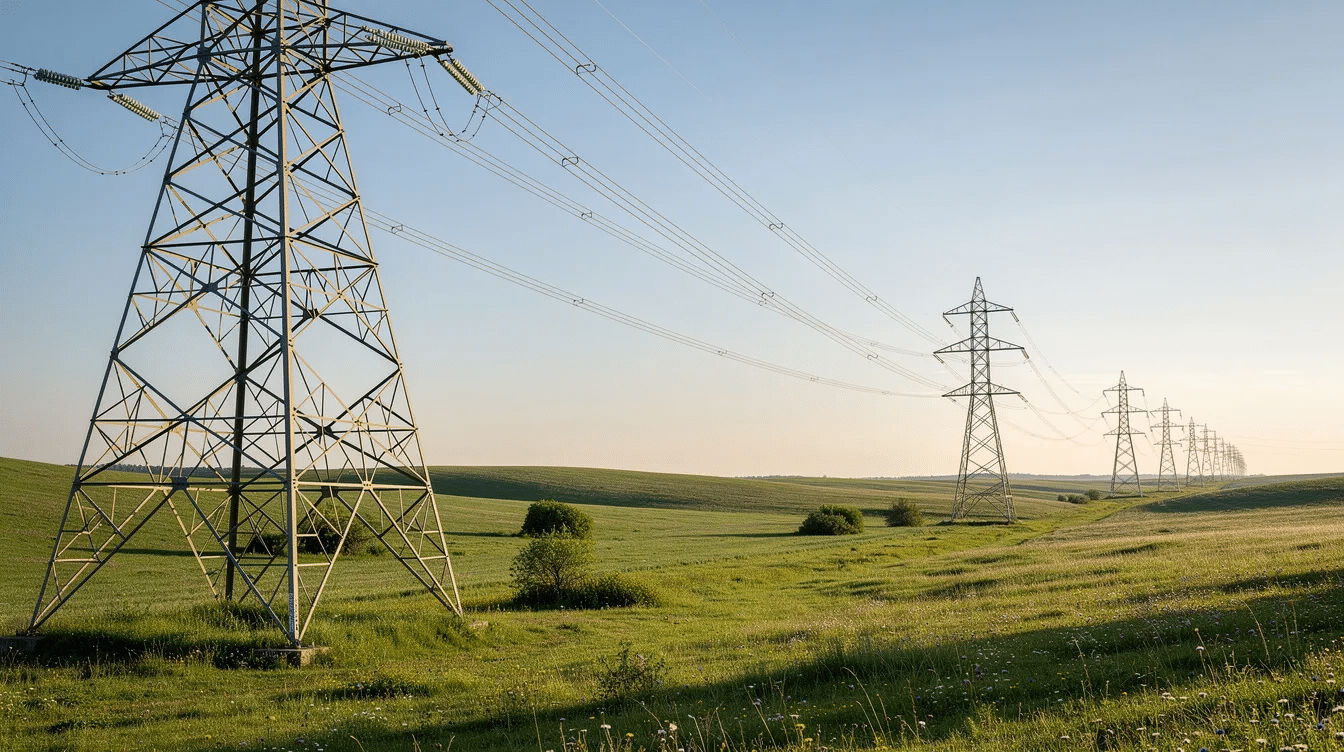
Power systems involve generation, transmission, and load flow of electricity. AC dominates power transmission because transformers can step voltage up or down. Raising voltage for long-distance transmission reduces current, which cuts I²R losses in the wires.
Power generated at plants at roughly 10 to 30 kV is stepped up to 120 to 700 kV for transmission, then stepped down at substations to distribution levels and finally to 120 or 230 V for end users. DC is common inside electronics, where rectifiers and regulators convert AC mains to stable DC.
Basic Electrical Circuits: Series, Parallel, and Mixed
An electrical circuit is a closed path that allows electric current to flow through components powered by a source. If the path is broken, you have an open circuit, which is incomplete and fails to work; no current flows.
Series circuits connect all components in a single path. The same current passes through every element, and voltage divides across them in proportion to their resistances. Example: two resistors of 2 Ω and 4 Ω in series with a 12 V supply produce a current of I = 12 / (2 + 4) = 2 A. The 2 Ω resistor drops 4 V; the 4 Ω resistor drops 8 V. The drops add to 12 V.
A parallel circuit provides multiple pathways for current flow. All branches share the same voltage, and current divides among them. Two resistors of 6 Ω and 12 Ω in parallel across 12 V draw 2 A and 1 A respectively; total current is 3 A. Total resistance: 1/Rtotal = 1/6 + 1/12 = 1/4, so Rtotal = 4 Ω.
Mixed circuits combine series and parallel configurations, which is how most real electrical systems are wired. A lighting circuit in a house, for example, runs parallel branches (each fixture) from a series feed protected by a single breaker.
Circuits are described using three structural elements: nodes (junctions where branches meet, also called common nodes), branches (paths containing components and wires), and loops (closed paths). These terms set up the next section on Kirchhoff’s laws.
Kirchhoff’s Laws and Circuit Analysis Basics
Kirchhoff’s Current Law (KCL) and Kirchhoff’s Voltage Law (KVL) are core tools in basic electrical engineering. Together with Ohm’s Law, they let you solve circuits with multiple loops, nodes, and sources.
Kirchhoff’s Current Law states total current in equals total current out at any node, reflecting conservation of electric charge. If 5 A enters a junction and 2 A leaves through one branch and 1 A through a second, then 2 A must leave through the third branch: 5 = 2 + 1 + 2.
Kirchhoff’s Voltage Law states total voltage around a loop equals zero, reflecting conservation of energy. In a loop containing a 12 V battery and two resistors (2 Ω and 4 Ω in series), writing the loop equation: +12 − 2I − 4I = 0, yielding I = 2 A.
These laws scale to complex networks. Circuit analysis techniques include nodal analysis (applying KCL at every node) and mesh analysis (applying KVL around every loop). For even more complex networks, Thevenin’s and Norton’s theorems simplify multi-source, multi-load circuits into equivalent single-source models. Sign conventions for current direction and voltage polarity must be defined consistently before writing equations.
AC Circuits: Phasors, Impedance, and Power
AC circuits in basic electrical engineering involve sinusoidal voltages and currents, typically described by amplitude, frequency, and phase. Steady-state AC analysis assumes transients have died out and all waveforms share the same frequency.
Phasors represent sinusoidal quantities as vectors with magnitude and phase angle, converting calculus-based differential equations into algebraic ones. A resistor’s voltage and current are in phase. An inductor’s current lags its voltage by 90°. A capacitor’s current leads its voltage by 90°.
Impedance (Z) is the AC equivalent of resistance. It combines resistance (R), inductive reactance (XL = ωL), and capacitive reactance (XC = 1/(ωC)). In a series AC circuit, Z = R + j(XL − XC), and its magnitude is √(R² + (XL − XC)²).
Power in alternating circuits splits into three quantities. Active power (measured in kW) does useful work. Reactive power (measured in kVAR) oscillates between source and reactive elements without performing work. Apparent power (measured in kVA) is the product of RMS voltage and RMS current.
Power factor equals active power divided by apparent power, or cos(φ), where φ is the phase angle between voltage and current. An industrial facility drawing 120 V RMS at 10 A with a 30° phase lag has an apparent power of 1200 VA but active power of only about 1039 W; the power factor is 0.866.
Fourier and Laplace transforms are used in signal analysis to break complex waveforms into frequency components, extending these AC fundamentals into broader electrical engineering applications.
Fundamental Electrical Components
Understanding the basics of passive components is essential for anyone working with electrical circuits.
Resistors limit current and set voltage levels. Every resistor has a resistance value, a tolerance, and a power rating (common ratings: ¼ W, ½ W, 1 W). Resistors dissipate energy as heat. Typical uses include voltage dividers, current limiting for LEDs, and biasing transistors. Resistance changes with temperature; metal-film resistors have a positive temperature coefficient.
Capacitors store energy in an electric field between two conductive plates separated by a dielectric. Capacitance is measured in farads, but circuit capacitors are typically in the microfarad to picofarad range. Capacitors block DC once charged and pass AC signals at a rate dependent on frequency. Uses include filtering power supply ripple, coupling signals between amplifier stages, and timing circuits.
Inductors store energy in a magnetic field generated by current flowing through a coil. Inductance is measured in henrys. Inductors pass DC freely in steady state but oppose changes in AC current, with reactance increasing at higher frequencies. Uses include filter chokes, energy transfer in switching power supplies, and transformer coupling.
These components behave differently in DC and AC circuits. In DC, capacitors charge and then block current; inductors initially resist current change but eventually act as short wires. In AC, both contribute reactance that varies with frequency.
Electrical Machines: Transformers, Motors, and Generators
Electrical machines convert electrical energy into mechanical energy and vice versa. They form the backbone of power systems and industrial applications worldwide. Electric motors consume roughly 60% of all generated electrical power; generators produce about 95% of the world’s electricity.
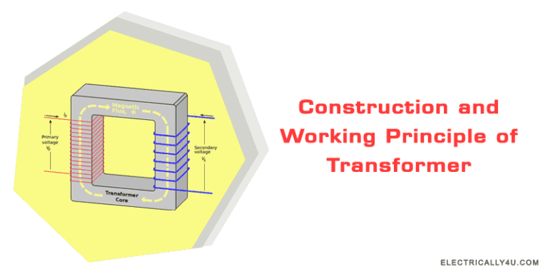
Transformers are static machines that adjust voltage levels in electrical power systems through electromagnetic induction, described by Faraday’s law and Lenz’s law. A transformer’s turns ratio (N₁/N₂) sets the voltage ratio.
A distribution transformer rated at 11 kV / 400 V with a turns ratio of 27.5:1 steps voltage down for neighborhood use. Large transformers achieve efficiencies above 95%, with losses split between copper losses (I²R in windings, varying with load) and core losses (hysteresis and eddy currents, nearly constant).
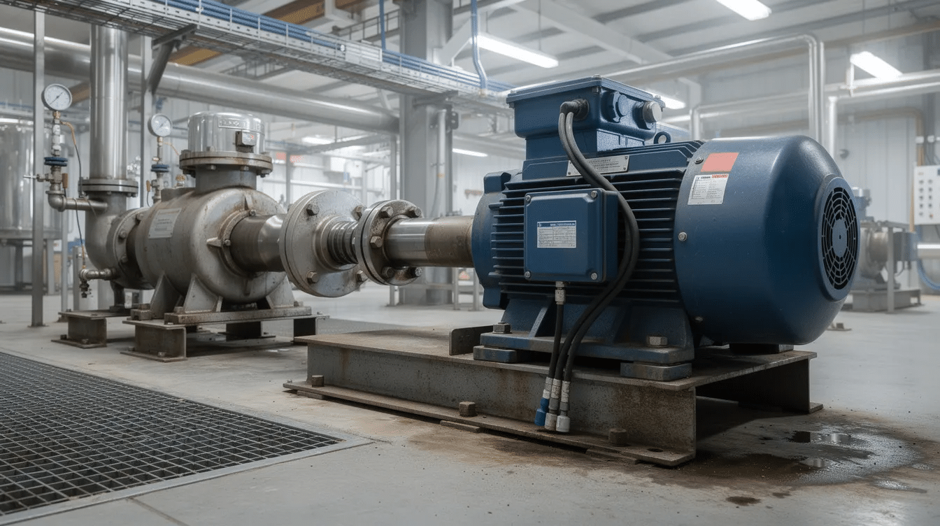
Electric motors convert electrical energy into mechanical motion. Induction motors are the workhorses of industry, driving pumps, fans, conveyors, and compressors. Key specifications include power rating (kW), torque (Nm), speed (RPM), and efficiency.
Generators convert mechanical motion into electrical energy, operating on the same electromagnetic principles as motors but in reverse. Power plants, wind turbines, and engine-driven backup sets all rely on generators.
Engineering design involves defining requirements and analyzing trade-offs during system development. Choosing a motor for a conveyor, for example, requires balancing torque, speed, efficiency, physical size, and cost.
Control Systems and Signals in Electrical Engineering
Control systems use feedback loops to regulate variables like speed, voltage, temperature, and position. An automatic voltage regulator on a generator measures output voltage and adjusts excitation to keep voltage within ±2% of the setpoint under changing loads. Cruise control in a vehicle measures actual speed, compares it to the driver’s target, and adjusts throttle to maintain the set speed.
Modern control systems combine sensors, actuators, controllers (PLCs, microcontrollers, DSPs), and communication networks. Sensors measure physical quantities; controllers process data and issue commands; actuators produce mechanical motion or other outputs.
Signals in these systems split into two types. Analog signals vary continuously in voltage or current. Digital signals take discrete levels, commonly logic 0 and logic 1. Digital systems are represented by binary and hexadecimal numbers. The boundary between analog and digital is bridged by analog-to-digital converters (ADCs) and digital-to-analog converters (DACs), which are present in nearly every modern electronic device.
Measurement, Tools, and Practical Lab Skills
Accurate measurement keeps electrical work safe and verifiable. Basic practical skills include using multimeters and oscilloscopes for testing circuits, and these two instruments cover most diagnostic needs.
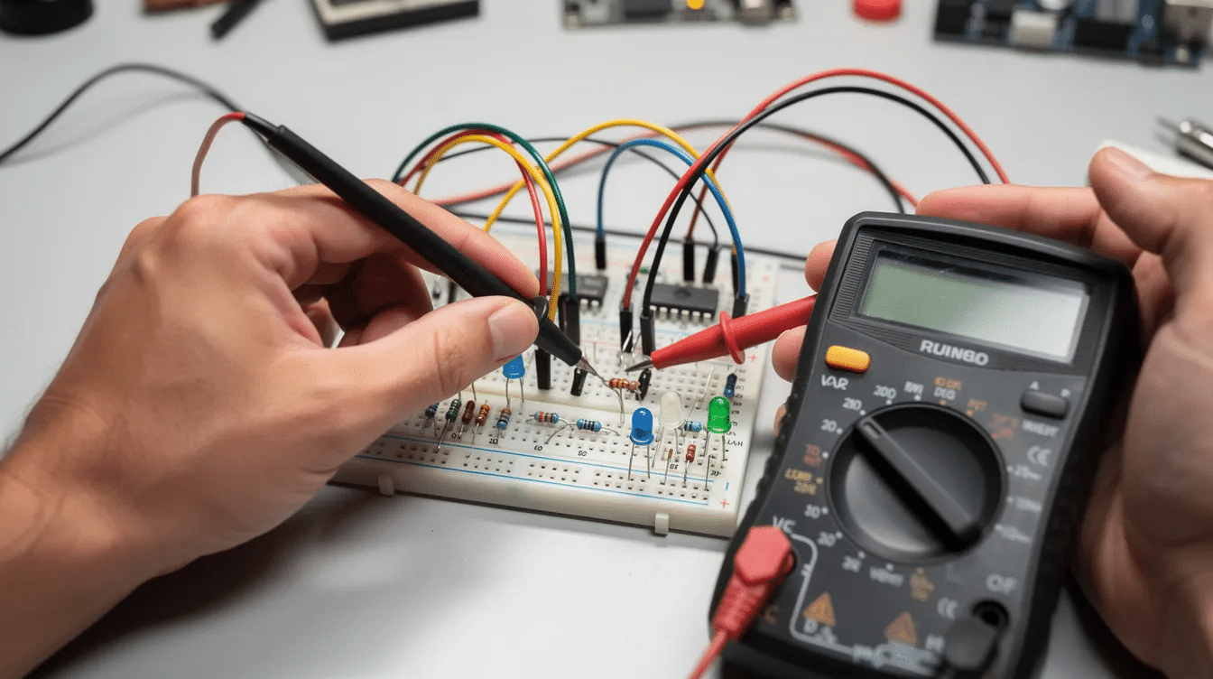
A multimeter measures voltage, current, and resistance. Before servicing any equipment, an engineer uses a multimeter to verify that no voltage is present. Checking a suspect resistor takes seconds: set the meter to ohms, place the probes across the component, and read the value.
An oscilloscope analyzes signal amplitude and frequency, displaying waveforms on screen. It is indispensable in AC circuits for checking phase relationships, transient behavior, and noise. A function generator provides test signals (sine, square, triangle) for driving circuits under controlled conditions. Spectrum analyzers are used in RF engineering for signal analysis across frequency bands.
Breadboards are used for prototyping electronic circuits. They allow you to build and modify DC and AC circuits without soldering. For permanent assemblies, soldering irons are essential for joining electronic components to printed circuit boards. Using proper wire gauge matters: cables must be sized to handle 125% of the load current to prevent overheating.
Power, Energy, and Efficiency
Electrical power is the rate of transferring electrical energy, calculated as P = V × I and measured in watts (W). A 120 V outlet supplying 10 A delivers 1200 W.
Electrical energy equals power multiplied by time. The standard billing unit is the kilowatt-hour (kWh). A 100 W lamp running for 10 hours uses 100 × 10 = 1000 Wh = 1 kWh.
Efficiency (η) equals useful output power divided by input power, expressed as a percentage. Every real device loses some energy. Joule’s Law states heat produced is proportional to I², R, and t (H = I²Rt), which is why conductors with even small resistance generate waste heat under load. Transformer copper losses, motor winding losses, and cable heating all follow this relationship.
Energy efficiency matters for cost, reliability, and sustainability. Large transformers operating near full load reach efficiencies above 95%. Small DC motors may reach only 70 to 90%. Minimizing losses in power systems, cables, and electrical machines directly reduces operating costs and heat that must be managed by cooling systems.
Electrical Safety Fundamentals
Safety is a non-negotiable part of electrical knowledge. The main hazards are electric shock (current flowing through the body), burns, arc flash, and fire from overloaded circuits, which can lead to electrical hazards including property damage and injury.
A short circuit occurs when current flows through an unintended low-resistance path, potentially causing equipment damage, fire, or injury. Overloaded circuits produce excess heat in wires and can ignite surrounding materials.
Core safety practices:
- Ensure power is off before working on electrical systems. Lock out and tag out the source.
- Use a multimeter to verify absence of voltage before touching conductors.
- Use insulated tools to prevent electrical accidents.
- Wear personal protective equipment, which includes insulated gloves and goggles rated for the voltage level.
- Water conducts electricity; keep surfaces dry to minimize shock risk.
Safety standards in electrical engineering include grounding and circuit protection. Earthing (grounding) provides a low-resistance path for fault currents to flow safely to ground. If insulation inside a metal-cased appliance fails, the grounding conductor carries fault current directly to earth, tripping the circuit breaker or blowing the fuse before a person touching the casing receives a shock. Fuses (one-time devices) and circuit breakers (resettable) interrupt overcurrent and protect both people and equipment.
Pathways to Becoming an Electrical Engineer
The typical route starts with a four- or five-year bachelor’s degree in electrical engineering. First-year courses cover calculus, differential equations, linear algebra, physics (with emphasis on electromagnetism and materials), and introductory programming.
Electrical engineers use programming languages for numerical computing and simulations; MATLAB, Python, and C are common choices. Electronic design automation tools (like SPICE simulators) appear in lab courses alongside physical hardware.
Core engineering courses in the second and third years include circuit analysis, electronic devices, digital logic, electromagnetics, control systems, and power systems. Lab work accompanies theory at every stage, reinforcing such topics as series circuit and parallel circuit behavior, AC impedance, and machine testing.
Early skill-building matters. Build small circuits: LED drivers, voltage dividers, basic amplifiers. Work with microcontrollers like Arduino. Join engineering clubs. Pursue internships at power plants, design firms, or test labs. A good understanding of fundamentals plus hands-on experience produces a working knowledge that textbooks alone cannot provide.
Mastering these core concepts opens doors across industries: renewable energy, smart grids, telecommunications, embedded electronics, automotive, robotics, and automation all require engineers with deep electrical knowledge.
Bringing It All Together: Core Concepts Checklist
This checklist summarizes the fundamental concepts covered above. Use it as a self-test before moving to more advanced study.
Foundations:
- Electric charge is the basis of all electrical phenomena; electricity is the flow of electric charge through conductors
- Electric current (A) = charge per second; voltage (V) = energy per charge; resistance (Ω) = opposition to current
- Ohm’s Law: V = I × R connects the three core quantities
Circuits and analysis:
- DC circuits carry current in one direction; AC circuits reverse direction at a set frequency
- Series circuits share current; parallel circuits share voltage; mixed circuits combine both
- KCL (current balance at nodes) and KVL (voltage balance around loops) solve multi-element circuits
- Impedance extends resistance to AC circuits, accounting for inductors and capacitors
Machines, components, and systems:
- Transformers, motors, and generators form the backbone of power and industrial systems
- Control systems use feedback to maintain setpoints; digital signals enable modern automation
- Resistors, capacitors, and inductors behave differently in DC steady-state vs. AC operation
Next steps for further information and in-depth study:
- Semiconductor devices (diodes, transistors) and integrated circuits
- Power electronics (rectifiers, inverters, switch-mode supplies)
- Three-phase systems and practical applications in industrial power
- Signal processing using Fourier and Laplace methods
Every advanced topic in electrical engineering, from renewable energy grid integration to embedded systems design, builds on these basics. Start with a breadboard, a multimeter, a handful of resistors, and a power supply. The rest follows from practice.