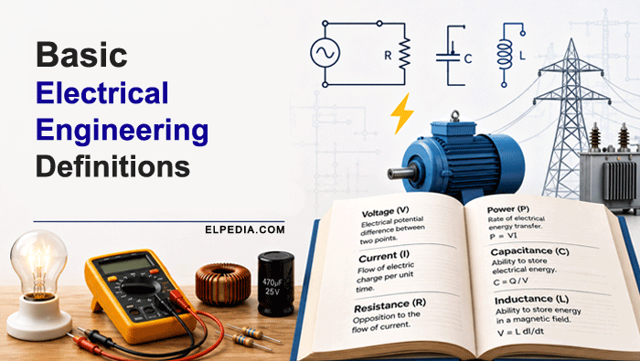
This article is a compact, glossary-style guide to basic electrical engineering definitions, organized by practical categories like electrical circuits, AC and DC, electrical machines, power systems, measurements and instrumentation, and safety.
You will learn core quantities – voltage, current, resistance, power, and electric charge – and how they connect through Ohm’s law (V = I × R) and electric power formulas that every electrical engineer uses daily.
Definitions are grouped into clusters such as “Electrical Circuits,” “Power Electronics,” “Digital Electronics” and “Measurements and Instrumentation,” making it easy for students, technicians, and early-career engineers to revise topic by topic.
Modern concepts like renewable energy, smart grids, and artificial intelligence in electrical engineering are also briefly defined, connecting fundamentals with latest technology.
The article closes with an FAQ section answering common beginner questions.
Introduction to Basic Electrical Engineering Terms
Mastering basic electrical engineering definitions is the first step for anyone working with electrical energy – whether you are a student, a technician, or an engineer preparing for a professional exam.
Electric power supports modern technology and infrastructure, and the vocabulary that describes it shows up in every circuit diagram, safety standard, and equipment datasheet you will ever read.
Electrical engineering is the discipline dealing with electricity, electric power, electronics, and electromagnetism. Electrical engineers design circuits, build power systems, develop telecommunications systems, and create control systems that keep modern society running.
In short, electrical engineers work across domains that range from integrated circuits inside personal computers to high-voltage power lines stretching across continents.
This article follows a categorized approach: “Electrical Circuits,” “AC and DC Terms,” “Electrical Machines,” “Power Electronics,” “Digital Electronics”, “Power System,” “Measurements and Instrumentation,” “Electrical Protection and Safety,” and “Renewable Energy and Modern Electrical Terms.”
Each section uses concise, exam-oriented bullet points aligned with standard sources and glossaries – no heavy math beyond Ohm’s law and the basic power formula. Think of it as a structured revision sheet you can scan in minutes or study section by section.
Core Electrical Quantities and Units
All later electrical engineering terms build on a handful of core physical quantities and their SI units. Understanding these is like learning the alphabet before reading – everything else follows.
Electric charge (symbol Q, unit coulomb, C) – Charge is a fundamental property of matter measured in coulombs. It comes in positive and negative forms. A single electron carries a charge of approximately 1.6 × 10⁻¹⁹ C.
Electric current (symbol I, unit ampere, A) – Current is the flow of electric charge, measured in amperes (A). It describes how much charge passes a point per second. Conventional current flow runs from positive to negative, opposite to actual electron flow.
Voltage / electric potential difference (symbol V, unit volt, V) – Voltage is measured in volts (V) and represents the work done per unit charge between two points. Think of it as the electrical pressure that pushes electrical current through a conductor.
Resistance (symbol R, unit ohm, Ω) – Electrical resistance is the opposition a material presents to current flow. Resistance is measured in ohms (Ω) and depends on the material’s resistivity, length, and cross-sectional area. Ohm’s law states V = I × R, meaning voltage is proportional to current through a resistor.
Conductance (symbol G, unit siemens, S) – The reciprocal of resistance. It measures how easily a circuit allows current and is useful in nodal circuit analysis and admittance calculations.
Electrical power (symbol P, unit watt, W) – Electric power is calculated as P = V × I, measured in watts (W). Equivalent forms include P = I²R and P = V²/R for resistive loads. Power is calculated as voltage (V) times current (A), and electrical power is measured in watts (W).
Electrical energy (unit joule, J; watt-hour, Wh; kilowatt-hour, kWh) – Energy is measured in watt-hours (Wh). One kWh equals 3.6 × 10⁶ joules and is the standard billing unit on residential electricity bills.
Other common units – Capacitance is measured in farads (F). Inductance is measured in henries (H). Frequency uses hertz (Hz), representing cycles per second. The joule (J) measures energy in the SI system.
Electrical Circuits: Structures and Laws
Electrical circuits provide controlled paths for current flow and are governed by a few key laws. Whether you are analyzing a simple flashlight or a complex electrical network, the same vocabulary and rules apply.
Electrical circuit – A closed path for electric current that includes a source (battery, generator), conductive path, and one or more loads (resistors, motors, lamps).
Node – A point where two or more circuit elements connect, used as a reference in circuit analysis.
Branch – A single element or series of elements between two nodes.
Loop / Mesh – A closed path within a circuit, used in mesh and loop analysis methods.
Series circuit – A series circuit connects components along a single path so the same current flows through every element. Example: old-style Christmas lights wired in series. If one component fails in a series circuit, the entire circuit stops.
Parallel circuit – In a parallel circuit, multiple pathways allow current flow and each component shares the same voltage. Example: home lighting circuits, where one bulb burning out does not affect the others. In parallel circuits, if one pathway fails, others remain functional.
Mixed circuits – Mixed circuits combine series and parallel connections, which is common in real electronic circuits and electrical systems.
Closed circuit – Path is complete and electricity flows through the conductors and load.
Open circuit – An open circuit is a break in the circuit path stopping the flow of current.
Short circuit – A short circuit is an abnormal low-resistance connection causing high current flows, potentially damaging equipment or starting fires. It is essentially a low resistance connection that bypasses the intended load.
Linear circuit – A circuit in which the output signals are directly proportional to the input signals. It typically include resistors, capacitors, inductors, and linear dependent sources.
Nonlinear circuit – A circuit where the output is not directly proportional to the input. It contain components like diodes, transistors, and other semiconductor devices that exhibit nonlinear voltage-current characteristics.
Active circuit – A circuit that contains at least one active component capable of supplying energy or power gain to the circuit. Active components include transistors, operational amplifiers, and integrated circuits.
Passive circuit – A circuit composed entirely of passive components that cannot supply energy but only consume, store, or dissipate it. Passive components include resistors, capacitors, inductors, and transformers.
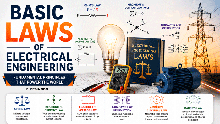
Kirchhoff’s Current Law (KCL) – Kirchhoff’s Current Law states that the total current entering a node equals the total current leaving it. It is the foundation of nodal analysis.
Kirchhoff’s Voltage Law (KVL) – Kirchhoff’s Voltage Law states the sum of all voltage drops around a closed loop equals zero. It is the basis of mesh or loop analysis.
Ohm’s law – Ohm’s law states V = I × R and applies to both DC and AC circuits (for the resistive component). It remains the basic building block for solving resistive circuits.
Series/parallel combinations – Resistors in series: resistances add (Req = R₁ + R₂ + …). Resistors in parallel: reciprocals add (1/Req = 1/R₁ + 1/R₂ + …). Capacitors combine in the opposite way (parallel capacitances add; series reciprocals add). Inductors combine like resistors, with caveats for magnetic coupling.
AC and DC Terms
The distinction between direct current and alternating current is one of the first things every electrical engineering student learns. DC powers most electronic devices and batteries, while AC dominates the world’s power grids and industrial machinery.
Direct current (DC) – Direct current flows in only one direction, typically from a battery or DC power supply. Most electronic circuits and electric vehicles run on DC.
Alternating current (AC) – Alternating current periodically reverses its direction, typically following a sinusoidal waveform. It reverses direction periodically, and nearly all national grids use AC at either 50 Hz or 60 Hz.
Single-phase system – An electrical power system using one alternating voltage waveform.
Three-phase system – A power system with three alternating voltages, each 120 degrees apart, used for efficient power distribution.
Frequency (f, unit hertz, Hz) – Frequency is the number of cycles per second measured in hertz. For example, 50 Hz means the signal varies continuously through 50 complete cycles every second.
Period (T) – The time for one complete cycle, related to frequency by T = 1/f. A 60 Hz signal has a period of about 16.7 milliseconds.
Amplitude / Peak value – The maximum voltage or current excursion from zero.
Peak-to-peak value – The total voltage or current swing in an AC waveform measured from its maximum positive peak to its maximum negative peak. It represents the full amplitude range of the signal.
RMS (root mean square) – The effective DC-equivalent value of an AC signal. Household outlets are rated in RMS: 230 V RMS in Europe, 120 V RMS in the US. The voltage developed across a load in an AC circuit is typically expressed in RMS terms.
Average value – The arithmetic mean of all instantaneous values of a waveform over one complete cycle. For a sinusoidal AC waveform, the average value of the absolute voltage or current is typically used.
Phase / Phase angle – In AC circuits, voltage and current may not peak simultaneously. The phase angle quantifies this shift, which becomes significant in inductive or capacitive loads.
Lagging current – Current that lags behind the voltage in phase, typical in inductive loads.
Leading current – Current that leads ahead of the voltage in phase, typical in capacitive loads.
Phase difference – The amount by which one AC waveform leads or lags another, measured in degrees or radians. It indicates the time shift between two periodic signals, important in analyzing circuits with reactive components.
Phase sequence – The order in which the voltages of a three-phase system reach their peak values.
Reactance – Opposition to AC from energy-storage elements: inductive reactance (XL = 2πfL) and capacitive reactance (XC = 1/(2πfC)). Reactance is frequency-dependent and measured in ohms.
Impedance (Z) – Impedance is the total opposition to AC combining resistance and reactance. It is expressed as a complex number; its magnitude sets current amplitude, its angle sets the phase shift.
Resonance – A condition in an electrical circuit where inductive and capacitive reactances are equal, causing maximum current or voltage.
Star connection – A method of connecting three electrical components with one common neutral point forming a ‘Y’ shape.
Delta connection – A method of connecting three components end-to-end in a closed loop forming a triangle.
Line voltage – The voltage measured between any two lines in a three-phase system.
Phase voltage – The voltage measured across a single component or phase in a system.
Line current – The current flowing through any one line conductor in a power system.
Phase current – The current flowing through a single phase or component.
Neutral – A common return path for current in an electrical system, often connected to earth ground.
Electrical Components and Circuit Design Basics
Basic electrical components are the building blocks of every circuit design in power, electronics, and control engineering. Understanding what each component does is essential before you can read a schematic or wire a prototype.
Conductor – A material that allows electricity to flow with little resistance. Conductors have free electrons that facilitate charge flow. Copper is a common conductor used in electrical systems; aluminum is another.
Insulator – A material that prevents the flow of electric current. Insulators lack free electrons, creating barriers to electricity. Rubber is a typical insulator used to coat wires; PVC and porcelain are other examples.
Switch – A device used to open or close an electrical circuit, thereby controlling the flow of current. Switches can be manual or automatic and come in various types, such as toggle, push-button, rotary, and slide switches. They are fundamental components for turning devices on or off and for selecting different circuit paths.
Resistor – A component designed to provide a specific electrical resistance, used to limit current, divide voltages, and bias circuits. Fixed, variable, and power resistors cover most circuit design needs.
Capacitor / Capacitance – Two conductors separated by an insulator (dielectric) that stores energy in the electric field. Capacitance can temporarily store electrical energy in an electric field and is central to filtering, timing circuits, and energy storage in power electronics.
Inductor / Inductance – A coil of wire that stores energy in a magnetic field. Inductance opposes changes in current and is measured in henries. Inductors are used in chokes, filters, and transformers.
Diode – A semiconductor device allowing current to flow in one direction only. Used in rectifiers, voltage clamping, and protection circuits throughout electronic circuits.
Transistor (BJT, MOSFET) – Active devices that amplify signals or switch current. MOSFETs dominate modern electronics and power electronics; BJTs remain common in analog design. Transistors are a foundational technology of modern electronics.
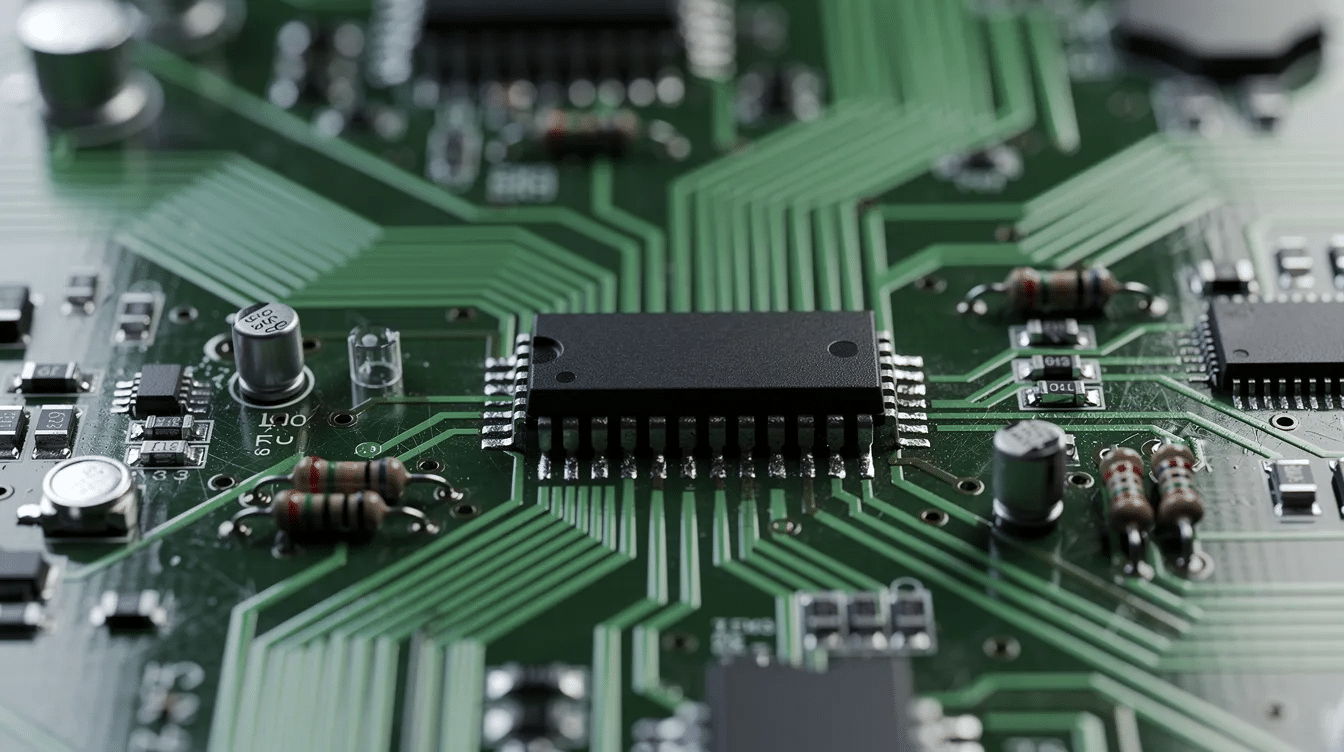
Integrated circuit (IC) – Semiconductor chips containing many components (transistors, resistors, capacitors) on a single die. Integrated circuits include microcontrollers, op-amps, and signal processing chips and are central to electronic devices from smartphones to industrial controllers.
Printed circuit board (PCB) – The physical platform that interconnects components via conductive traces, used in virtually every electrical device you encounter.
Electromagnetism and Magnetic Quantities
Electromagnetic principles underlie transformers, motors, generators, and many sensors. Without electromagnetism, there would be no way to convert power between electrical and mechanical forms.
Magnetic field – A region around a magnet or current-carrying conductor where magnetic forces act. Electromagnetic waves propagate through oscillating electric and magnetic fields.
Magnetic flux (Φ, unit weber, Wb) – The total magnetic field passing through a given area, analogous to the amount of “magnetic flow” through a coil.
Magnetic flux density (B, unit tesla, T) – The strength of the magnetic field per unit area within a material or free space.
Electromotive force (EMF) – The voltage developed by a source such as a battery or generator through electromagnetic induction or chemical reaction. EMF is measured in volts, like ordinary voltage.
Faraday’s law – A changing magnetic flux through a circuit induces an EMF proportional to the rate of change. This principle is the basis for generators and transformers.
Lenz’s law – The direction of the induced EMF opposes the change in magnetic flux that produced it. This explains eddy-current braking and the opposing torque in generators.
Inductance (magnetic perspective) – Inductance is the property where a change in current induces a voltage, measured in henries. Self-inductance describes a coil opposing its own current changes; mutual inductance describes coupling between coils (transformer action).
Magnetic hysteresis and core losses – Real magnetic core materials lose energy as heat during each magnetization cycle. These core losses, along with eddy-current losses, reduce the efficiency of transformers and electrical machines.
Electrical Machines: Motors, Generators, and Transformers
Electrical machines convert electrical energy to mechanical energy (motors) or mechanical energy to electrical energy (generators). Transformers transfer AC power between different voltage levels without any moving parts. Together, these machines form the backbone of every power system.
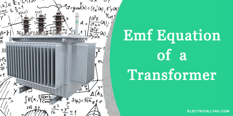
Transformer – A static electromagnetic device that transfers AC power between circuits at different voltage levels via mutual induction. It has primary and secondary windings wound on a shared magnetic core.
Step-up transformer – Increases voltage (and correspondingly decreases current). Used at generating stations to step voltage up to transmission levels of hundreds of kV.
Step-down transformer – Decreases voltage for safer distribution and end use. Your phone charger contains a tiny step-down converter, while large distribution transformers feed neighborhoods.
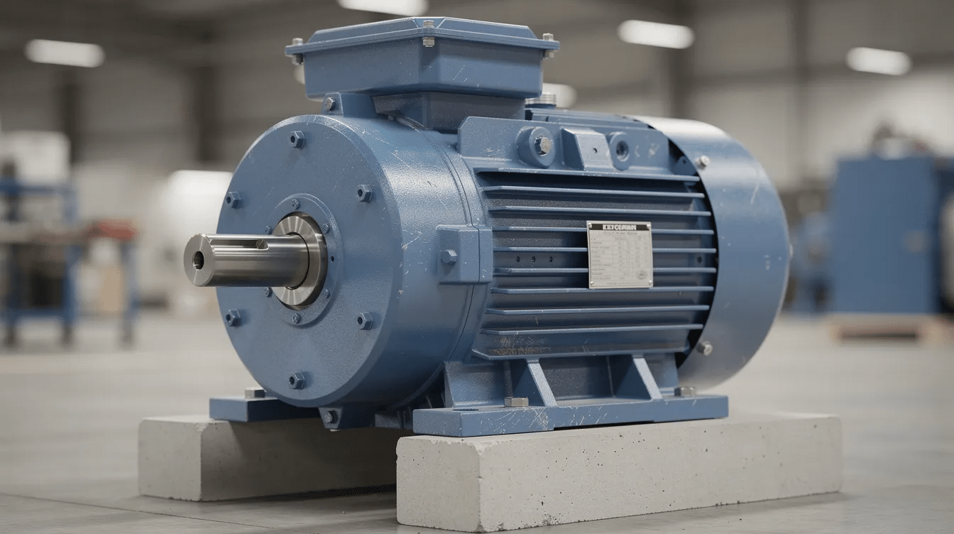
Electric motor – A machine that converts electric power into mechanical rotation or torque. Types include DC motors, AC induction motors, and synchronous motors, powering everything from fans and elevators to industrial machinery.
Electric generator / Alternator – The reverse of a motor: converts mechanical energy from turbines into electrical energy. Alternators in power plants produce the AC that reaches your outlets.
Synchronous machine – Rotor speed exactly matches the rotating magnetic field speed. Common in large power plants and used for voltage regulation.
Induction (asynchronous) machine – Rotor speed slightly lags the field speed. Robust, affordable, and the most widely used motor type in industry.
Synchronous speed – The speed at which the magnetic field in an AC machine rotates, determined by the supply frequency and the number of poles. It is given by the formula Ns = 120f / P, where Ns is synchronous speed in RPM, f is frequency in hertz, and P is the number of poles.
Slip – The percentage difference between synchronous speed and actual rotor speed in an induction motor; essential for torque production.
Back EMF (Electromotive Force) – The voltage generated in the armature winding of a motor that opposes the applied voltage. It is proportional to the motor’s speed and acts to reduce the net voltage and current flowing through the motor.
Torque – A measure of the rotational force produced by an electrical machine, such as a motor or generator. It is the product of force and the distance from the pivot point, typically measured in newton-meters (Nm).
Armature reaction – The effect of the magnetic field produced by the armature current on the distribution of the main magnetic flux in a machine. It can distort and weaken the main field, affecting performance and causing voltage regulation issues.
Commutation – The process of reversing the direction of current in the armature windings of a DC machine to maintain unidirectional torque. It is achieved using a commutator and brushes, ensuring smooth operation of the motor or generator.
Eddy current loss – Eddy current loss is the energy lost due to circulating currents induced within the core or conductive parts of electrical machines and transformers when exposed to a changing magnetic field. These currents generate heat and reduce the efficiency of the machine. Eddy current losses are minimized by using laminated cores or materials with high electrical resistance
Efficiency (η) – Output power divided by input power, expressed as a percentage. High-quality machines exceed 90% efficiency; losses include copper (winding), iron (core), and friction losses.
Power Electronics and Conversion Devices
Power electronics handles the conversion and control of electric power using semiconductor switching devices. Every time you charge a phone, drive an electric vehicle, or adjust a fan’s speed, power electronics is at work.
Rectifier – A circuit that converts AC to DC, typically using diodes or controlled devices like SCRs. Single-phase and three-phase rectifiers serve everything from laptop chargers to industrial DC supplies.
Inverter – A power electronic device that converts DC to AC. Inverters are essential in solar PV systems, UPS units, and variable-speed motor drives, and they convert power from one form to another efficiently.
Chopper (DC–DC converter) – A circuit that converts one DC voltage level to another using high-frequency switching of MOSFETs or IGBTs.
Converter (general) – An umbrella term covering AC–DC, DC–AC, AC–AC, and DC–DC conversion. Context determines the specific type.
Key switching devices – Thyristors (SCRs) handle high-power controlled rectification. IGBTs combine high voltage capability with fast switching for motor drives. Power MOSFETs dominate lower-voltage, high-frequency applications. All are built on semiconductor chips.
Pulse-width modulation (PWM) – A technique controlling average output voltage by varying the duty cycle of a switching waveform. PWM is used in motor speed control, switched-mode power supplies (SMPS), and LED dimming.
Harmonics and power quality – Switching converters inject harmonic currents into the grid, distorting waveforms and increasing losses. Grid codes and filters are used to keep power quality within acceptable limits.
Digital Electronics
Digital electronics is a branch of electrical engineering that deals with circuits and systems operating on discrete signal levels, primarily using binary numbers. It forms the foundation of modern computing, communication, and control systems. Digital electronics enables reliable data processing, storage, and transmission through logical operations on bits.
Digital signal – A signal that has discrete levels or values, typically representing binary 0s and 1s, used in digital circuits for information processing.
Analog signal – A continuous signal that varies smoothly over time and can take any value within a range, as opposed to discrete digital levels.
Binary number system – A numbering system using only two digits, 0 and 1, to represent all numbers and data in digital electronics.
Bit – The smallest unit of digital information, representing a single binary value of 0 or 1.
Byte – A group of 8 bits, commonly used as a basic unit of data storage and processing.
Logic level – The voltage or signal level representing a binary state in a digital circuit, typically defined as logic 0 or logic 1.
Logic 0 – The binary state representing a low voltage level or false condition in digital logic.
Logic 1 – The binary state representing a high voltage level or true condition in digital logic.
Digital circuit – An electronic circuit designed to operate on digital signals, performing logical operations and data manipulation.
Logic gate – A fundamental digital circuit element that performs a basic logical function such as AND, OR, NOT, NAND, NOR, XOR, or XNOR.
Boolean algebra – A branch of algebra dealing with variables that have two possible values (true/false or 1/0) and logical operations.
Boolean function – A mathematical expression using Boolean variables and operations that defines a logical relationship.
Truth table – A tabular representation listing all possible input combinations to a logic circuit and their corresponding output values.
Combinational circuit – A digital circuit whose output depends only on the current inputs, without memory or feedback.
Sequential circuit – A digital circuit whose output depends on current inputs and past input history, incorporating memory elements.
Flip-flop – A basic sequential circuit element capable of storing one bit of data, used as a memory element in registers and counters.
Multiplexer (MUX) – A combinational circuit that selects one input from multiple inputs and forwards it to a single output line based on select signals.
Decoder – A combinational circuit that converts binary coded inputs into a corresponding unique output line, often used for address decoding.
Register – A group of flip-flops used to store multiple bits of data.
Counter – A sequential circuit that counts pulses and represents the count in binary or other formats.
Shift register – A register that shifts stored bits left or right by one position upon clock pulses.
Clock signal – A timing signal used to synchronize operations in sequential digital circuits.
Pulse – A brief change in signal level used to trigger or synchronize digital circuits.
Latch – A memory device similar to a flip-flop but level-triggered rather than edge-triggered.
Edge-triggered – Describes a device or circuit that changes state only at the transition (rising or falling edge) of a clock signal.
Setup time – The minimum time before the clock edge that data must be stable for reliable operation of sequential circuits.
Hold time – The minimum time after the clock edge that data must remain stable.
Fan-out – The number of inputs of a logic gate or circuit that a single output can drive without degradation.
Propagation delay – The time taken for an input change to produce a corresponding output change in a digital circuit.
Noise margin – The tolerance of a digital circuit to noise without causing errors in logic levels.
Power System Fundamentals
A power system is the interconnected electrical network that generates, transmits, and distributes electric power from power plants to end-users. Understanding power systems is critical because these networks are the infrastructure maintaining modern civilization’s access to electricity.
Generating station (power plant) – Facilities where electricity is generated by power plants and renewable sources. Examples include thermal (coal, gas), hydroelectric, nuclear, wind farms, and solar PV plants.
Transmission system – High-voltage power lines and substations (e.g., 132 kV, 220 kV, 400 kV, 765 kV) moving bulk electrical energy over long distances. Higher voltage means lower current for the same power, reducing losses.
Distribution system – Medium- and low-voltage networks (e.g., 11 kV feeders, 400/230 V for homes) delivering power to consumers.
Substation – A facility in the power system where voltage is transformed from high to low or vice versa using transformers, and where switching, protection, and control equipment are housed. Substations connect transmission lines to distribution networks and help regulate power flow.
Grid – The interconnected network of power generation plants, transmission lines, substations, and distribution systems that deliver electricity from producers to consumers over a wide geographic area. The grid ensures reliable and continuous power supply.
Feeder – A power line that carries electricity from a substation to distribution points or directly to a load center. Feeders operate at medium voltage levels and serve as the main arteries of the distribution system.
Distributor – A conductor or set of conductors that branch off from a feeder to supply electricity to individual consumers or groups of loads. Distributors operate at lower voltages and provide the final stage of power delivery.
Service mains – The cables or conductors that connect the distributor to the consumer’s premises, delivering electrical energy for use in homes, businesses, or industries.
Busbar – A metallic conductor bar in substations or switchgear that collects and distributes electric power among incoming and outgoing circuits.
Load – Any electrical device or group of devices consuming electrical power: residential, commercial, or industrial loads.
Maximum demand – The highest level of electrical power or current drawn by a consumer or system during a specified period, usually measured in kilowatts (kW) or amperes (A). It is critical for designing electrical infrastructure and billing.
Load factor – The ratio of the average load over a given period to the maximum demand during that period. It indicates how efficiently the electrical system’s capacity is utilized.
Demand factor – The ratio of the maximum demand of a system or part of the system to the total connected load. It reflects the diversity and simultaneity of usage.
Diversity factor – The ratio of the sum of individual maximum demands of various subdivisions of a system to the maximum demand of the whole system. It is always greater than or equal to one and accounts for the fact that not all loads peak simultaneously.
Power factor (cos φ) – The ratio of real power (kW) to apparent power (kVA). A low power factor means higher currents and losses; utilities may charge penalties for poor power factor.
Real (active) power (P, kW) – The power that does actual work: heating, lighting, mechanical motion.
Reactive power (Q, kVAR) – Power that oscillates between source and inductive or capacitive loads, doing no net work but necessary for maintaining magnetic and electrical fields.
Apparent power (S, kVA) – The product of RMS voltage and RMS current regardless of phase. Equipment ratings (transformers, cables) are based on apparent power.
Balanced vs unbalanced loads – In three-phase systems, balanced loads draw equal current in each phase. Unbalanced loads create neutral currents and can cause overheating and inefficiency.
Measurements and Instrumentation
Accurate measurements of voltage, current, power, and energy are essential for safe operation, troubleshooting, and billing in electrical systems. The right test equipment turns abstract physical quantities into actionable numbers.
Instrument transformer – Devices that scale high currents or voltages to safely measurable levels. A current transformer (CT) measures current; a potential/voltage transformer (PT or VT) measures voltage.
Ammeter – Measures electric current; connected in series with the circuit. Always check the instrument’s range before connecting.
Voltmeter – Measures electric potential difference across a component; connected in parallel.
Wattmeter – Measures real power in watts or kilowatts, accounting for phase in AC circuits. Used in labs and energy audits.
Energy meter (kWh meter) – The device utilities use to measure cumulative electrical energy consumption for billing.
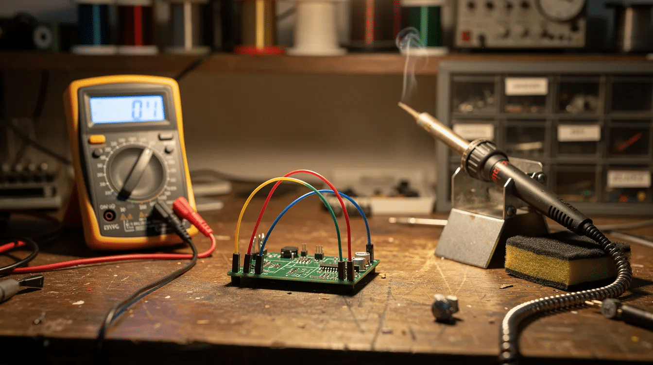
Multimeter – A portable instrument that can measure voltage, current, and resistance (and often capacitance, diode forward voltage, and continuity). It is the most common piece of test equipment for troubleshooting.
Oscilloscope – Displays voltage versus time on a screen, allowing engineers to observe waveform shape, amplitude, frequency, and phase. Indispensable in signal processing and circuit design debugging.
Accuracy class – Defines the permissible measurement error of an instrument transformer, specified by standards (e.g., Class 0.5, Class 1).
Burden – The load (in VA) the instrument transformer secondary must drive; exceeding the rated burden degrades accuracy.
Electrical Protection and Safety Devices
Electrical protection and safety are core responsibilities of every electrical engineer. Properly selected and coordinated protective devices prevent fires, equipment damage, and electric shock.
Fuse – A sacrificial overcurrent device that melts and opens the circuit when current exceeds a rated value. Available in fast-acting and slow-blow types.
Circuit breaker – A switchgear device (an electrically operated switch at its core) that automatically interrupts current during faults or overloads. Common types include MCB (miniature circuit breaker) and MCCB (moulded case circuit breaker).
Relay – An electrically operated switch or sensing device used in protection and control functions. Modern numerical relays can handle overcurrent, differential, and distance protection in one unit.
Overcurrent / short-circuit current / fault current – Overcurrent is any current exceeding the allowed magnitude. Short-circuit current is the extreme case flowing through a low resistance connection. Protective devices are coordinated to clear faults within milliseconds when current exceeds safe limits.
Earthing (grounding) – Intentional connection of system parts to earth ground to limit touch voltages and ensure safety during faults.
Earth fault – An unintended connection between a live conductor and earth.
Touch voltage – The voltage a person may experience when touching an energized surface during a fault.
Step voltage – The potential difference between two feet on the ground near a fault, relevant in substation safety.
RCD (Residual Current Device) / ELCB (Earth Leakage Circuit Breaker) – A residual current device disconnects supply when leakage current to earth exceeds a safe limit (e.g., 30 mA for personal protection), helping to ensure safety against electric shock.
MCB (Miniature CB) – An automatic electrical switch designed to protect an electrical circuit from damage caused by overload or short circuit. It interrupts current flow when it detects faults, typically used in residential and commercial low-voltage applications.
MCCB (Molded Case CB) – It provides protection by automatically switching off electrical power in the event of overload or short circuit. It is used for higher current ratings than MCBs and is common in industrial and large commercial installations.
RCCB (Residual Current CB) – It disconnects a circuit whenever it detects leakage current to earth (ground), which could cause electric shock.
Protection coordination / selectivity – Devices are graded so the one closest to the fault trips first, preventing unnecessary outages upstream.
Safety Practices and Standards in Electrical Engineering
Beyond hardware devices, safe electrical work practices and standards prevent accidents. Electrical shocks can cause severe injuries or death, making procedural discipline just as important as the right fuse or breaker.
Safe isolation (lockout/tagout) – A step-by-step procedure to ensure that circuits are de-energized and cannot be re-energized while work is in progress. Always ensure the power supply is disconnected before working on circuits.
Personal protective equipment (PPE) – Personal protective equipment includes insulated gloves and goggles, as well as arc-rated clothing, safety shoes, and insulated tools. Proper safety gear is crucial when handling electrical systems.
Creepage distance and clearance – Minimum distances along insulating surfaces (creepage) and through air (clearance) that prevent surface tracking and air-gap breakdown.
Standards – National and international wiring regulations (IEC standards, NEC, BS 7671) define safe installation and equipment requirements. Compliance is not optional in professional electrical work.
Shock hazard – Risk of current passing through the body, potentially causing burns, cardiac arrest, or death. Even low-voltage systems like 230 V AC can be lethal.
Arc-flash hazard – An arc flash releases intense heat and light during a short circuit or fault. Specialized PPE and approach boundaries are required.
Education and training – Education and training are essential for electrical safety. Electrical engineers must combine knowledge of protective devices (fuses, circuit breakers, RCDs) with procedural knowledge (permits, risk assessments) for holistic safety.
Control Engineering and Automation Terms
Control engineering deals with making systems automatically maintain desired outputs. It is a key area for electrical engineers working in robotics, process control, mechatronics, and power system regulation. Control systems keep turbines at the right speed, factories at the right temperature, and electronic systems at stable operating points.
Control system – An arrangement of components that manages, commands, or regulates the behavior of other devices (e.g., motor speed control, temperature regulation in industrial processes).
Open-loop control – Output does not influence the input. Example: a simple timer turning on a heater for a fixed period.
Closed-loop (feedback) control – Output is measured and fed back to adjust the input. Example: a thermostat measuring room temperature and switching heating on or off.
Feedback – The process of feeding a portion of the output back to the input. Negative feedback reduces error and stabilizes; positive feedback amplifies deviation.
Setpoint, process variable, error signal – The setpoint is the desired value, the process variable is the measured value, and the error signal is their difference.
Controller (e.g., PID) – A device applying proportional, integral, and derivative actions to the error signal to drive the process variable toward the setpoint.
Actuator – The element that physically implements control functions – a motor, valve, or relay that converts controller output into physical action.
Sensor / Transducer – Devices converting physical quantities (temperature, position, speed) into electrical signals for the control system.
PLC and microcontroller – Programmable logic controllers handle industrial automation (assembly lines, water treatment). Microcontrollers handle embedded control in consumer electronic devices and audio equipment.
Renewable Energy and Modern Electrical Engineering Terms
Since roughly 2010, rapid growth of solar and wind power has added new vocabulary to everyday electrical engineering practice. These terms connect classical fundamentals with the technology shaping the grid of the 2020s and beyond.
Renewable energy – Electric power derived from sources naturally replenished: solar, wind, small hydro, and biomass. Increasingly central to generation planning worldwide.
Photovoltaic (PV) cell / module / array – A PV cell converts sunlight into DC electricity via a semiconductor junction. Modules are panels; arrays are collections. DC output requires inverters for AC grid connection.
Wind turbine – An electromechanical system converting kinetic energy of wind into electrical energy via a generator. Variable-speed designs use power electronics for grid compatibility, making wind power a rapidly growing source.
Maximum Power Point Tracking (MPPT) – A technique used in photovoltaic systems and other renewable energy sources to continuously adjust the electrical operating point of the modules or arrays to ensure they deliver the maximum possible power under varying conditions such as sunlight intensity and temperature.
Smart grid – An electricity network that uses digital communication, sensors, and control to improve reliability, efficiency, and integration of distributed energy resources. Smart grids support wireless communication networks between substations, meters, and control centers.
Microgrid – A localized group of electricity sources and loads that normally operates connected to and synchronous with the traditional centralized grid but can disconnect and function autonomously as physical and/or economic conditions dictate. Microgrids enhance reliability, integrate distributed generation, and support renewable energy use.
Hybrid Renewable Energy System (HRES) – An energy system that combines two or more renewable energy sources, such as solar, wind, and biomass, often with energy storage and conventional generators, to provide a more reliable and stable power supply, especially in remote or off-grid locations.
Distributed generation (DG) – Small-scale generation units connected near the load – rooftop solar, diesel gensets, fuel cells. DG raises issues of bidirectional power flow and local voltage regulation.
Energy storage systems (ESS) – Battery energy storage (e.g., lithium-ion), pumped hydro, and flywheels balance intermittent renewable generation and maintain grid stability.
Net metering / Feed-in tariff – Policy mechanisms allowing small producers to sell surplus energy to the grid or receive billing credits, varying by jurisdiction.
Electric vehicles (EVs) and EV chargers – EVs represent growing loads and potential vehicle-to-grid storage. Chargers involve AC–DC and DC–DC power electronics and require dedicated standards.
Artificial Intelligence and Digital Tools in Electrical Engineering
Artificial intelligence, machine learning, and data-driven methods increasingly support design, operation, and optimization of power systems and electrical equipment. These digital tools are transforming how electrical engineers work, turning raw data into actionable insight.
Artificial intelligence (AI) – Computer systems performing tasks that typically require human intelligence: pattern recognition, prediction, decision-making. AI is being embedded across power system operations and circuit design automation.
Machine learning (ML) – A subset of AI where algorithms learn from data. In electrical engineering, ML supports load forecasting, fault detection, and optimization of electronic systems.
Digital twin – A virtual model of a physical system (transformer, wind farm, industrial plant) used for simulation, what-if analysis, and optimization. Digital twins reduce commissioning time and improve predictive maintenance.
Power system state estimation – A computational process using measurements and models to estimate voltages and power flows across a grid in real time.
Condition monitoring and predictive maintenance – Sensors and AI algorithms monitor transformer oil temperature, motor vibration, and circuit breaker condition to predict failures before they happen, reducing unplanned outages.
AI and control engineering – Adaptive control and reinforcement learning enable complex, nonlinear systems to self-tune – relevant to robotics, laser systems, and advanced grid management.
Study Tips for Learning Electrical Engineering Terms
Memorizing long lists of electrical engineering terms becomes much easier when definitions are grouped by topic and tied to practical examples.
Organize terms by the same categories used in this article (circuits, machines, power electronics, safety, etc.) instead of alphabetically.
Use flashcards: one side has the term (e.g., “impedance”), the other has the concise definition, symbol, and unit.
Draw simple sketches – circuit diagrams, motor cross-sections, phasor diagrams – to reinforce definitions visually.
Solve basic numeric problems involving voltage, current, resistance, and power. Even one or two quick calculations per term anchors the concept.
Link each definition to a real device: “circuit breaker” → your home distribution panel; “transformer” → the box on a utility pole or your laptop charger.
Read datasheets and lab manuals to see these electrical engineering terms used in realistic engineering language. Understanding the electrical field becomes second nature with consistent exposure.
Practice explaining terms out loud. If you can teach it, you know it.
Frequently Asked Questions (FAQ)
Start with core quantities: voltage, current, resistance, power, energy, and frequency. Then learn the relationships that tie them together – Ohm’s law (V = I × R) and the basic power formula (P = V × I).
Next, pick up essential component names: resistor, capacitor, inductor, diode, transistor, transformer, circuit breaker, and fuse, since they appear on nearly every circuit diagram.
After that, move on to AC versus DC concepts, series and parallel circuits, and simple safety terms like earthing and short circuit. Following the section order of this article provides a logical learning path.
Electrical engineering terms typically relate to high-power systems and electrical energy – generators, transformers, transmission lines, power factor, and protection devices.
Electronics engineering terms focus on low-power signal processing and circuit design – op-amps, digital logic, microcontrollers, and communication systems.
There is strong overlap: components like diodes, transistors, and MOSFETs plus concepts like impedance and feedback appear in both fields, just at different power and voltage scales.
Modern degree programs often combine both under “electrical and electronics engineering,” so beginners should be comfortable with vocabulary from both domains. For grid and power system roles, power-system and safety terminology is crucial; for embedded-system roles, analog and digital circuit design terms matter more.
Control engineering maintains stable voltage, frequency, and power flows through automatic controllers in generators, transformers, and loads – examples include automatic voltage regulators and turbine governor control.
Artificial intelligence and machine learning help forecast load and renewable generation, detect incipient faults, optimize switching operations, and support smart grid management. Modern utilities feed data from sensors, smart meters, and protection relays into algorithms for state estimation, contingency analysis, and predictive maintenance.
Understanding the basic terms from this article – like power factor, busbar, relay, and inverter – makes it much easier to study advanced AI-based grid applications later in your career and contribute to a connected world powered by intelligent electrical systems.
Observe laboratory equipment – multimeters, oscilloscopes, power supplies, transformers, motors – and consciously name every electrical engineering term that applies. Walk through a household distribution board (under supervision) and identify circuit breakers, RCDs, busbars, and earthing connections.
Read a simple datasheet for a component such as a motor or MOSFET and spot terms like rated current, voltage, power, impedance, and protection type. Small hands-on projects, like wiring a DC circuit on a breadboard or programming a microcontroller to control an LED, let you tie each step back to the definitions learned. Mechanical engineers crossing into electrical work benefit from the same approach – building familiarity one component at a time.
An Assistant Professor in Electrical and Electronics Engineering, Certified Energy Manager, Photoshop Designer, Blogger, and Founder of Elpedia, passionate about simplifying and sharing knowledge in Electrical and Electronics Engineering.